UNO-2484G_V2 User Manual 78
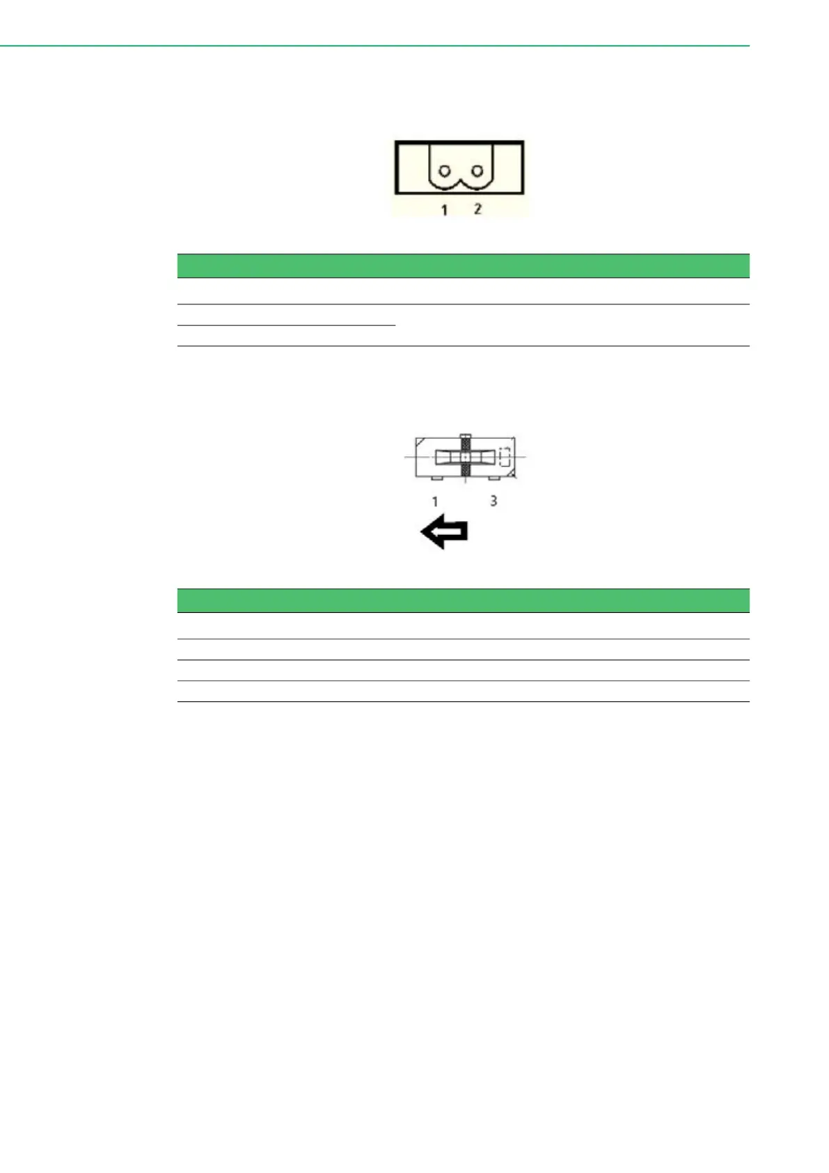
A.1 Power Connector (DCIN1)
A.2 Clear CMOS Function (CMOS1)
Table A.1: Power Connector Pin Assignments
Pin Signal Description
1 Power IN V+
10 - 36 V
DC
2 Power IN V- (GND)
Table A.2: Clear CMOS Function (CMOS1)
CMOS1 CMOS Clear Function
Description This jumper is used to select CMOS Clear Enable/Disable
(2-3) Enable (Clear CMOS)
(1-2) Disable (Default)