ix UNO-2484G_V2 User Manual
Contents
Chapter 1 Overview...............................................1
1.1 Introduction ............................................................................................... 2
1.2 Safety Precautions.................................................................................... 2
1.3 Packing List............................................................................................... 3
1.4 Hardware Specifications ........................................................................... 3
1.4.1 General ......................................................................................... 3
Table 1.1: General....................................................................... 3
1.4.2 System Hardware ......................................................................... 3
Table 1.2: System Hardware....................................................... 3
1.4.3 I/O Interfaces ................................................................................ 4
Table 1.3: I/O Interfaces.............................................................. 4
1.4.4 Environment.................................................................................. 4
Table 1.4: I/O Interfaces.............................................................. 4
1.4.5 Certification................................................................................... 4
Table 1.5: Certification................................................................. 4
1.4.6 Extension Kit (Optional) ................................................................ 4
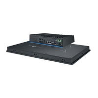
1.5 Dimensions ............................................................................................... 5
Figure 1.1 UNO-2484G V2 Dimensions ...................................... 5
Figure 1.2 UNO-2484G V2 Dimensions (with optional extension
kit)............................................................................... 5
Chapter 2 Hardware Functionality.......................7
2.1 Introduction ............................................................................................... 8
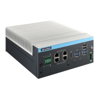
Figure 2.1 Front Panel of UNO-2484G V2................................... 8
Figure 2.2 Rear Panel of UNO-2484G V2 ................................... 8
2.2 Serial Communication Ports...................................................................... 8
2.2.1 COM Port Interfaces (COM1, COM2, COM3, COM4) .................. 8
2.2.2 Power Connector .......................................................................... 8
2.2.3 LAN: Ethernet Connector.............................................................. 8
2.2.4 USB Connector............................................................................. 9
2.2.5 HDMI Connector ........................................................................... 9
2.2.6 DP Connector ............................................................................... 9
2.2.7 RTC Battery .................................................................................. 9
2.2.8 Power Button/Power Management ............................................... 9
2.2.9 Reset Button ................................................................................. 9
2.2.10 mPCIe Connector ......................................................................... 9
2.2.11 M.2 B-key Connector .................................................................... 9
2.2.12 M.2 M-key Connector.................................................................. 10
2.2.13 Nano SIM Slot............................................................................. 10
2.2.14 LED Indicators ............................................................................ 10
2.3 Base Unit’s Internal Connectors.............................................................. 10
Figure 2.3 Diagram of Connector Locations on UNO-2484G V2
(Top Side)................................................................. 10
Figure 2.4 Diagram of Key Components Location on UNO-2484G
V2 (Bottom Side ....................................................... 11
Table 2.1: Connectors and Jumpers ......................................... 11
Chapter 3 Initial Setup ........................................13
3.1 Chassis Grounding.................................................................................. 14
Figure 3.1 Chassis Grounding Connection................................ 14
3.2 Connect the Power Supply...................................................................... 15