28
Ground Resistance Tester Model 6471
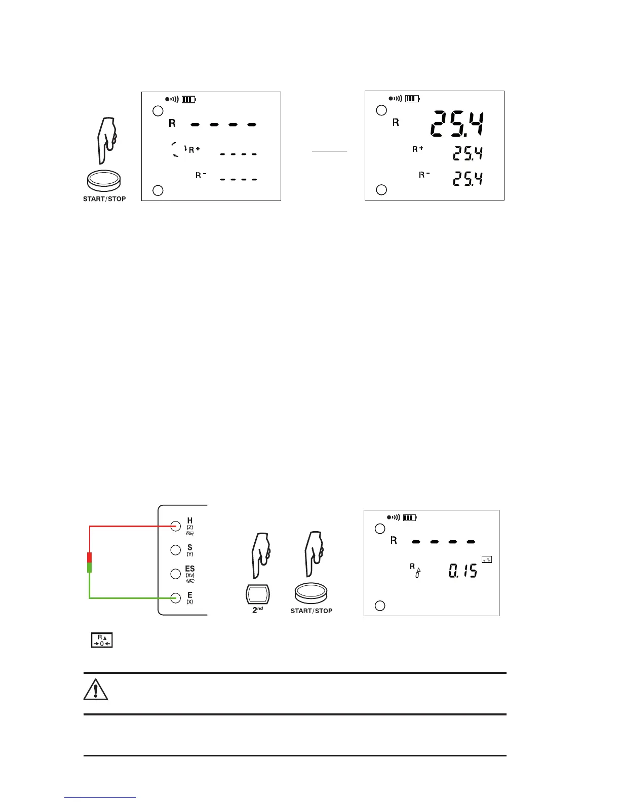
3. The 6471 makes a measurement with a positive current (R+), then reverses the
direction of the current and makes another measurement with negative (R-).
R =
(R+) + (R-)
2
Ω
DC
ALARM
Ω
Ω
H
E
±
AUTO
Ω
DC
ALARM
Ω
Ω
H
E
±
AUTO
4. To display the measurement parameters, press DISPLAY several times.
The device displays the following parameters:
R+, R-, +U
H-E
, +I
H-E
, -U
H-E
, -I
H-E
, U-Act (U
H-E
and its frequency) and R
∆0
if there
is compensation for the measurement leads.
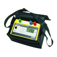
5.2.1 Lead Compensation Measurement
Lead compensation subtracts the resistance of the test leads from the measured
result.
• Short the two measurement leads connected to H (Z) and E (X) terminals.
• Press the 2nd button, then the START/STOP button to start the measure-
ment.
• This value will be deducted from all resistance values measured thereafter
until the rotary switch is turned to another function.
AUTO
0
R
Ω
DC
AC
ALARM
Ω
H
E
±
appears on the display after the compensation value has been measured.
NOTE: If the compensation resistance is > 5Ω, or if the leads are not shorted
when the measurement is started, the value of compensation will be canceled.
www.ShopAEMC.com
Shop for AEMC products online at:
1.888.610.7664