Ground Resistance Tester Model 6471
47
6.4 3-Pole Earth/Ground Measurements & Coupling
6.4.1 3-Pole Earth/Ground Measurements
Pressing on Hz/OPTIONS in MANUAL mode allows the following parameters to
be changed using the ► button:
• EARTH blinks Earth Coupling Measurement
• 128 Hz blinks Test Frequency Measurement
• Test voltage blinks Test Voltage Selection
6.4.2 Earth/Ground Coupling Measurements
This measurement calls for making and storing three intermediate measurements
(at the same frequency). It is available only in MANUAL mode.
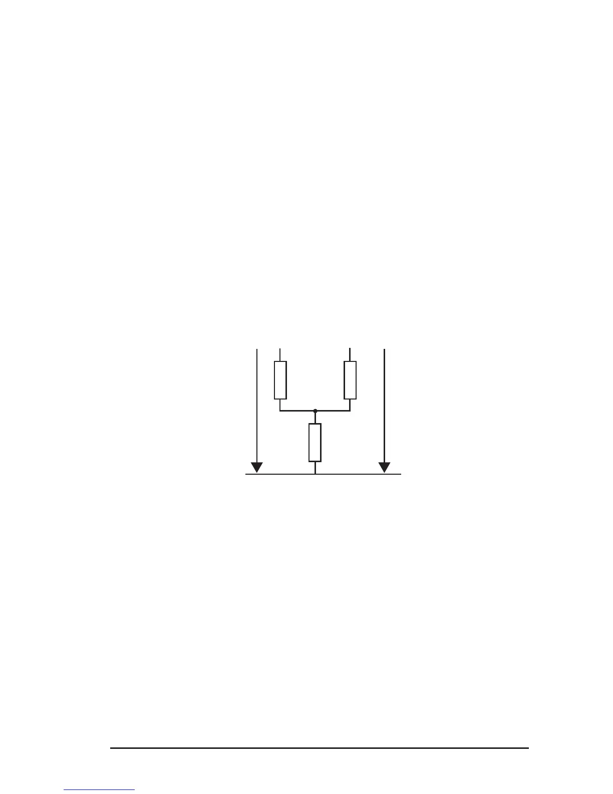
Connection diagram:
R
C
R
2
R
b
R
1-2
R
A
R
1
#1
Press Hz/OPTIONS and use the ► button to switch from EARTH to EARTH COU-
PLING. Proceed as follows:
• If you want to eliminate the resistance of the measurement leads, you can
use lead compensation (2nd + START) before starting the actual coupling
measurement (see § 5.2.1).
• Turn the rotary switch to 3-Pole.
• Select a test frequency and a test voltage (if desired).
• The screen displays EARTH COUPLING 1. Make a 3-pole earth measure-
ment on the rst earth system (measurement of R
1
in the connection dia-
gram on previous page).
• Stop the measurement by pressing the START/STOP button. The MEM
symbol ashes to indicate that this result must be recorded in memory.
Press the MEM button twice. To save to another location, refer to §7.1.
www.ShopAEMC.com
Shop for AEMC products online at:
1.888.610.7664