58
Ground Resistance Tester Model 6471
The Ground Tester Control Panel opens and displays the following:
• A shortcut toolbar.
• A toolbar with the mode selection and start/stop buttons.
• The instrument's status window (on the left-hand side):
- Recorded data from the instrument
- Real-time data
- Connection status
- The communications port and speed of the connection
- The model number, serial number, and rmware version
- Date and time from the clock
- Battery status
• Conguration window that shows all of the parameters available for modi-
cation. This window defaults to the instrument mode that is selected.
• Real-time Measurement window that shows the measurement of each test
performed in real-time (available only after a test has been performed).
If the indicated items are not shown on the screen, select Restore Default Layout
from the Window menu.
8.3.1 Establishing Communication to the Instrument
If the instrument is turned ON at the time the Ground Tester Control Panel is
opened, a communication link will happen automatically.
If the instrument is turned OFF at the time the Control Panel is opened, establish a
communication link by going to Instrument > Connect in the main menu.
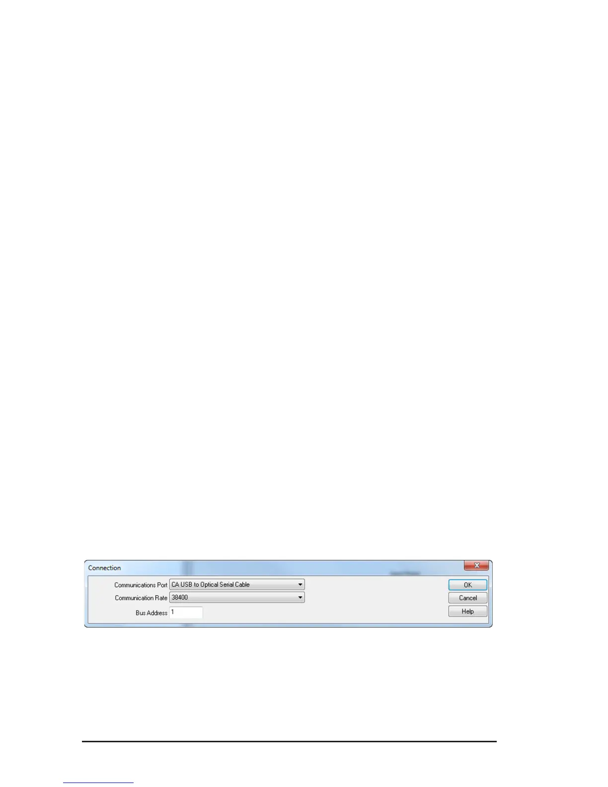
• The Communication dialog box will appear. Make sure that the communica-
tion port displayed in the dialog box matches the port that the serial cable is
plugged into.
Figure 8-5
• Once the proper communication parameters have been specied, click OK.
www.ShopAEMC.com
Shop for AEMC products online at:
1.888.610.7664