Ground Resistance Tester Model 6471
37
4. Clamp to the path of the earth electrode to be checked, then connect a lead
from the current clamp to this same point [connection to terminal ES (XV) ].
Take care not to place the cable of electrode H (Z) too close to the current
clamp in order to avoid any transmission of the AC signal to the clamp (espe-
cially when using an MN82 clamp).
5.
Start the measurement by pressing the START/STOP button.
H
S
ES
E
AUTO
Ω
mA
mV
R
SEL
= R
E1
6.
You can now move the clamp and its lead to measure the other earth resist-
ances, R
E2
, R
E3
, etc.
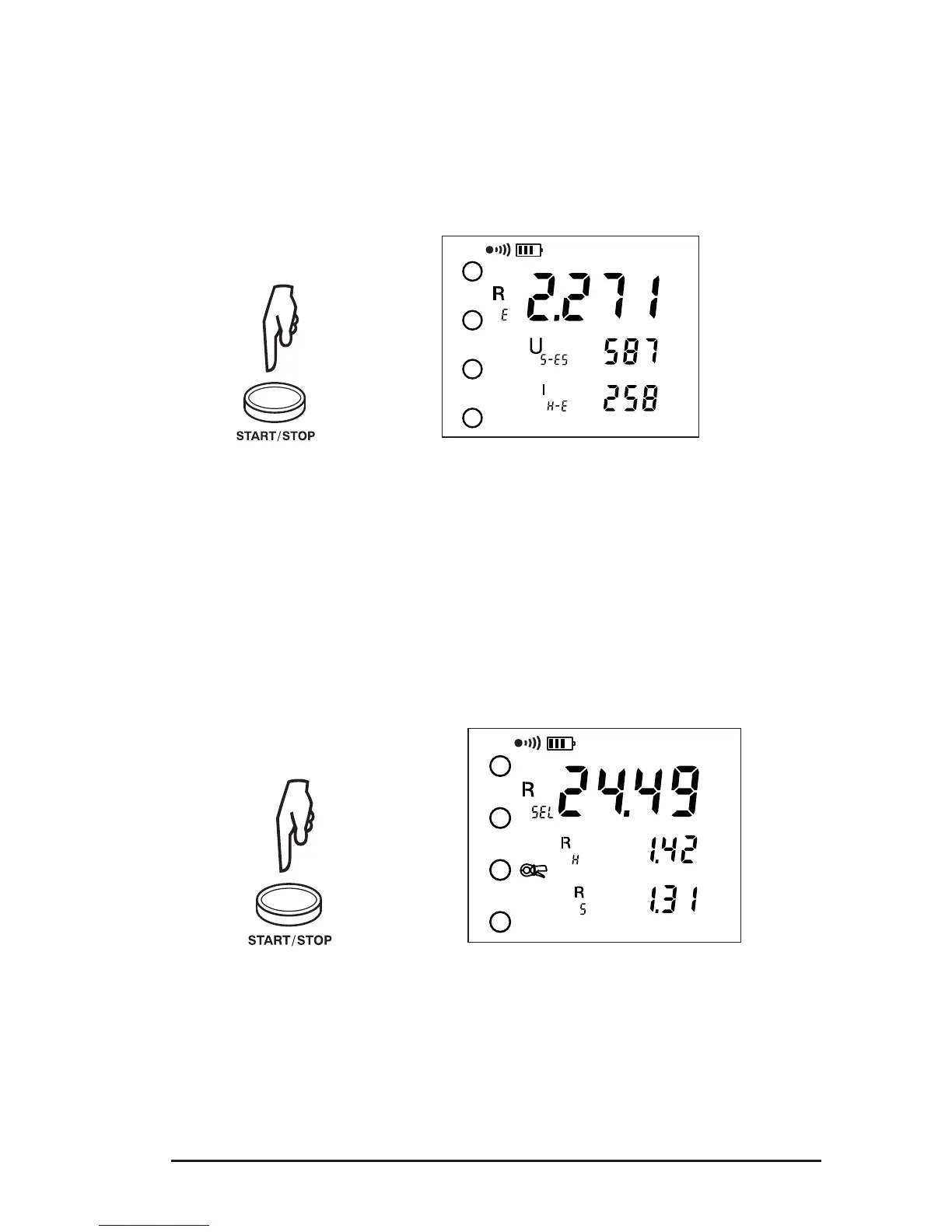
7.
To display the measurement parameters, press DISPLAY several times.
The device displays the following parameters:
R
SEL
, U
S-ES
, I
H-E
, R-Act (R
PASS
), U-Act (U
H-E
and its frequency), I-Act (I
ES
and its
frequency).
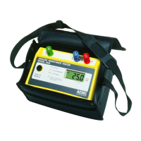
To measure the resistances of auxiliary electrodes H (Z) and S (Y), or if the resis-
tance of the electrodes is too large (see § 10.1), start the measurement with a long
press of the START/STOP button.
R
E
, R
H
, R
S
, U
E-S
will be displayed.
> 2s
H
S
ES
E
AUTO
Ω
kΩ
kΩ
www.ShopAEMC.com
Shop for AEMC products online at:
1.888.610.7664