BC 2000 DIGITAL
Audio Routing, Mixing and Processing System for Program Production Centers
HARDWARE MANUAL
87
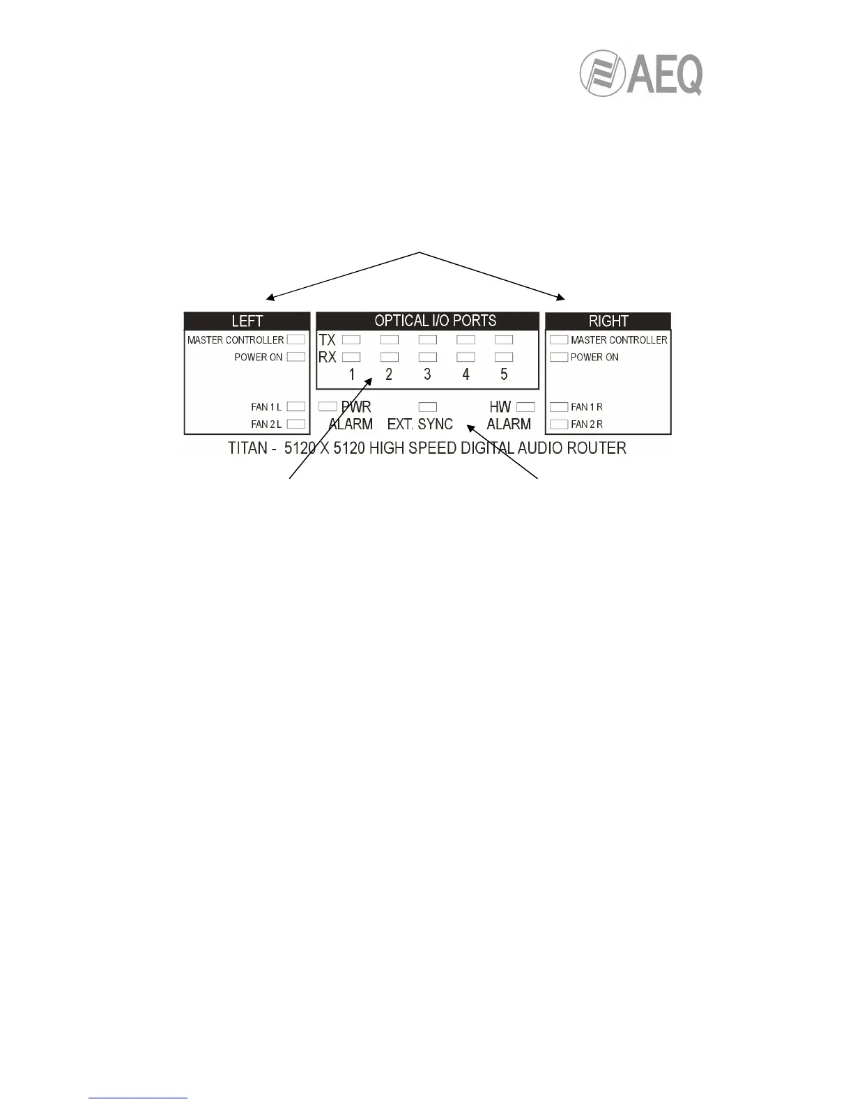
when lighted in
green indicate communication between
each one of the 5 bi-directional optical
fiber ports and the associated BC2213
module.
When ‘TX’ LED turns to red indicates
an alarm in the corresponding optical
fiber transmitter.
When ‘RX’ LED turns to red indicates
an alarm in the optical fiber receiver
because no reception signal is
detected.
indicate which controller module (left or
right) is working as master (LED on) or slave (LED off).
'POWER ON' LEDs: indicate the presence of feed power form each
power supply.
'FAN 1L', 'FAN 2L', 'FAN 1R' y 'FAN 2R' LEDs: indicate a failure in one
of the 4 system ventilation fans when turning to red.
indicates a
power supply failure (for instance, one
of the two power supplies is not
working or is switched off).
'EXT. SYNC' LED: indicates that the
system synchronism clock is external.
'HW ALARM' LED: indicates that the
audio router is not working, that the
hardware configuration for its correct
operation has failed.