AEQ BC-2500
Radio Broadcast Mixing Desk
13
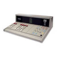
5.1.2. Description of Controls and Connectors.
2
3
4
5
6
7
8
10
9
11
12
13
14
15
16
17
18
19
1.- Input switch MICRO/LINE
2.- Gain adjusting potentiometer GAIN
3.- Radiofrequency switch HFF
4.- Treble frequency level adjusting potentiometer TREBLE
5.- Middle frequency parametric equalizer potentiometer
MID/FREQ
6.- Middle frequency level adjusting potentiometer MID/GAIN
7.- Bass frequency level adjusting potentiometer BASS
8.- Equalizer activation switch EQ.ON
9.- Saturation level led indicator CLIP
10.- Send to auxiliary 1 bus potentiometer AUX. 1
11.- Send to auxiliary 2 bus potentiometer AUX. 2
12.- Balance level adjusting potentiometer BALANCE
13.- Send to master 1 output bus switch MASTER 1
14.- Send to master 2 output bus switch MASTER 2
15.- Send to telephone bus switch PHONE
16.- Send to pre-listen bus push-button PFL ON
17.- Pre-listen active led indicator PFL ON
18.- Channel activation switch CHANNEL ON
19.- Output level slide potentiometer FADER
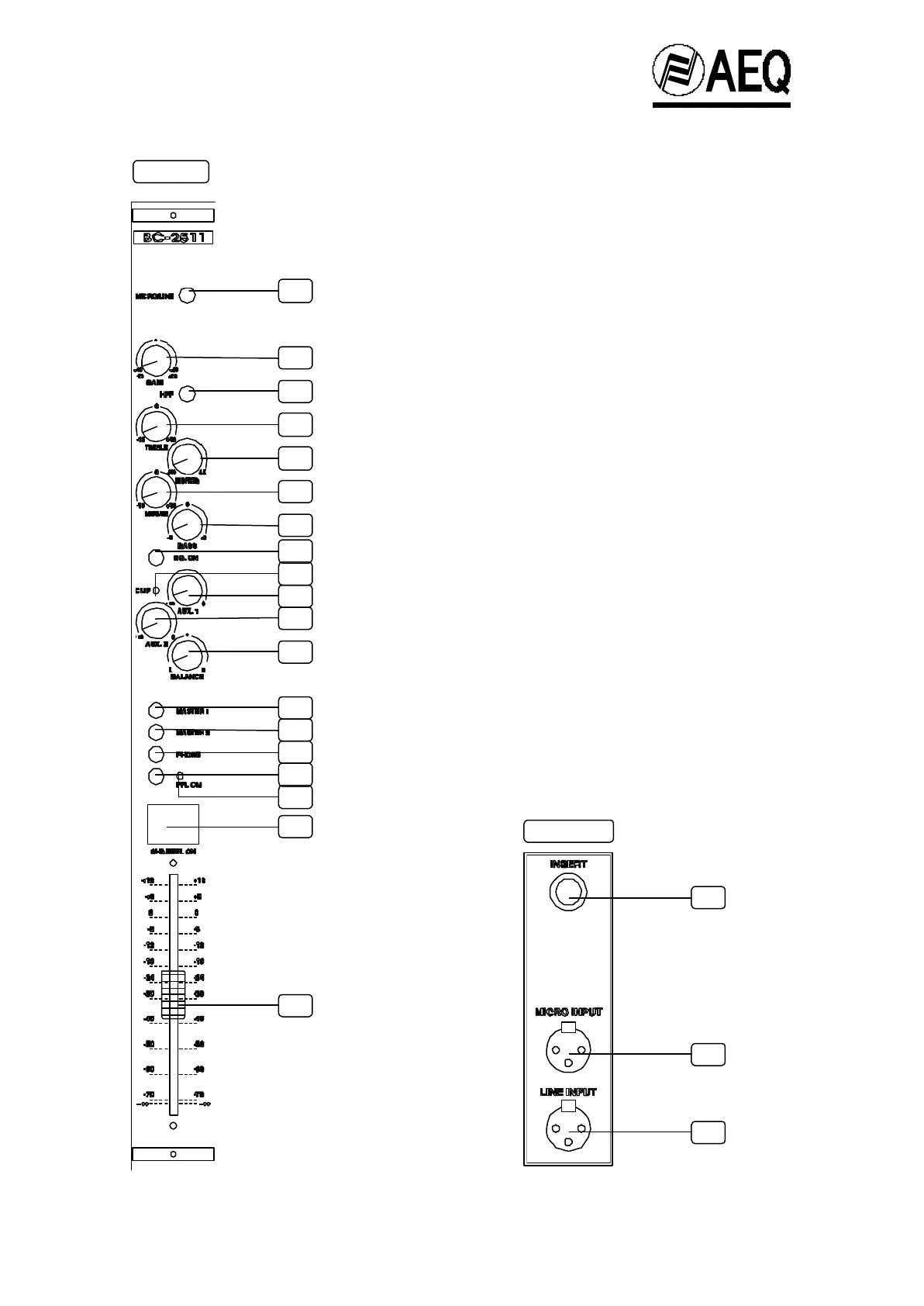
20.- Input/output connector socket INSERT
21.- Microphone input connector MICRO
22.- Line input connector LINE
20
21
22
REAR
FRONT
 Loading...