AEQ BC-2500
Radio Broadcast Mixing Desk
32
5.7.1.4. Signal, Studio and Control Monitor cut Administration Block
This block administers the Control and Studio monitor cut and Signal circuits.
There are two independents signal “ON AIR” circuits, Studio and Control that is activated when
signals are received from programmed BC-2511, BC-2521 and BC-2522 input modules.
The rear panel houses the connectors necessary to feed a direct 24-volt power supply,
without external transformers or relays, to two luminous signaling circuits.
Each of the CONTROL and STUDIO circuits is provided with connections for two signal outputs,
(1) BREAK, (2) MAKE and (3) COMMON.
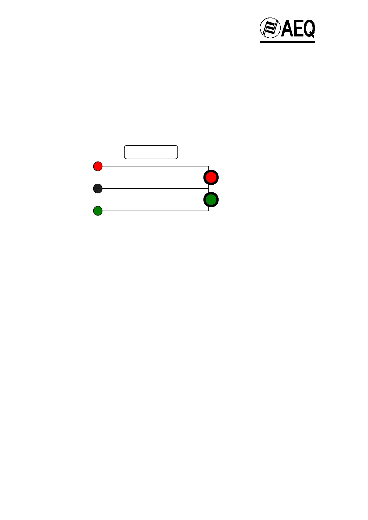
Operational outline diagram of the CONTROL circuit:
A potential difference of 24 volts exists between the MAKE and COMMON connectors when one of
the programmed channel is active (see Section 7.1.). When the programmed channels are
disabled the BREAK and COMMON outputs will have a potential difference of 24 volts.
The functional diagram for the STUDIO circuit is similar to the channels that are
programmed to activate the signal circuits.
This block also administers the CONTROL and STUDIO monitor cut. The operation is associated
to the activation of the signal circuits, i.e. when the Control circuit output MAKE is activated, the
output to the monitors in the same area is deactivated. This avoids the possibility of the monitors
feeding back to the microphones connected to the channels programmed to function in the Control
area in order to operate in the zone of Control.
The operation of STUDIO monitor cut is similar for the channels that are programmed to operate in
the Studio area.
Note: The maximum permissible combined 24V circuit load is 30VA. For higher loads an external
relay must be used.
Note: The fuse that protects the 24v circuit is located in the BC2523 power supply module. See
chapter 5.8.2.
BREAK
COMMON
MAKE
SIGNAL
SIGNAL
CONTROL
 Loading...