AEQ BC-2500
Radio Broadcast Mixing Desk
14
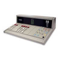
5.2. BC-2521 DOUBLE LINE EQUALIZED STEREO INPUT MODULE.
5.2.1. Functional description
The Double Line Equalized Stereo Input Module BC-2521 permits the connection of two
stereo inputs A and B. These lines are connected to (23) INPUT A (L) and (24) INPUT A (R) for
the left and right Line A channels and (26) INPUT B (L) and (27) INPUT B (R) for the left and rigth
Line B channels, selection is by switch (1) INPUT A/B. If the selector is at rest input A is active,
when the selector is depressed input B is selected.
The gain of the selected input is adjusted with potentiometer (3) GAIN.
It is possible to convert this signal to mono by activating switch (2) ST/MONO
Switch (4) HFF activates a radiofrequency filter. (100 Hz)
Subsequently the equalization can be adjusted by the potentiometers (5, 6, 7 and 8) TREBLE,
MID/FREQ, MID/GAIN & BASS, corresponding to the treble level, mid frequencies, mid
frequencies gain and bass level, respectively, whenever the equalization circuit is activated by the
switch (9) EQ ON.
With the aim of avoiding saturation a led indicator (10) CLIP illuminates on reaching
maximum signal level. If required this signal can be monitored by activating Push-button (18) PFL
ON, to send it to the pre-listen bus. This status is confirmed by the illumination of led indicator
(19).
Potentiometer (12) BALANCE regulates the left/right channel output signal balance. This
function is activated when switch (14) BALANCE ON is activated.
The output signal can be directed to the following outputs whenever the operative switch
(20) CHANNEL ON is activated:
Master 1, adjusts the send level with fader (21) and pushing the switch (15) MASTER 1
Master 2, adjusts the send level with fader (21) and pushing the switch (16) MASTER 2
Telephone buses 1 and 2, adjust the send level with fader (21) and pushing the switch (17)
PHONE.
This signal can also be sent to the following auxiliary outputs:
Auxiliary 1, the send level is adjusted with potentiometer (11) AUX 1 if working with the Auxiliary 1
send programmed pre-fader or the send level is adjusted with fader (21) once the send level to
Auxiliary bus 1 is set with potentiometer (11) AUX 1 when working with the send to auxiliary 1
programmed as post-fader and whenever the channel operative switch (20) CHANNEL ON is
activated.
Auxiliary 2, the send level is adjusted with potentiometer (12) AUX 2 if working with the
Auxiliary 2 send programmed pre-fader or the send level is adjusted with fader (21) once the send
level to Auxiliary bus 1 is set with potentiometer (12) AUX 2 when working with the send to
auxiliary 1 programmed as post-fader and whenever the channel operative switch (20) CHANNEL
ON is activated.
The position of the programming bridges and their functions are described in Section 7 of
this manual.
 Loading...