Benchmark 6000 Boiler Installation, Operation & Maintenance Manual
CHAPTER 3 – OPERATION
Page 52 of 210 AERCO International, Inc. • 100 Oritani Dr. • Blauvelt, NY 10913 OMM-0086_0D
03/20/14 Ph.: 800-526-0288 GF-133
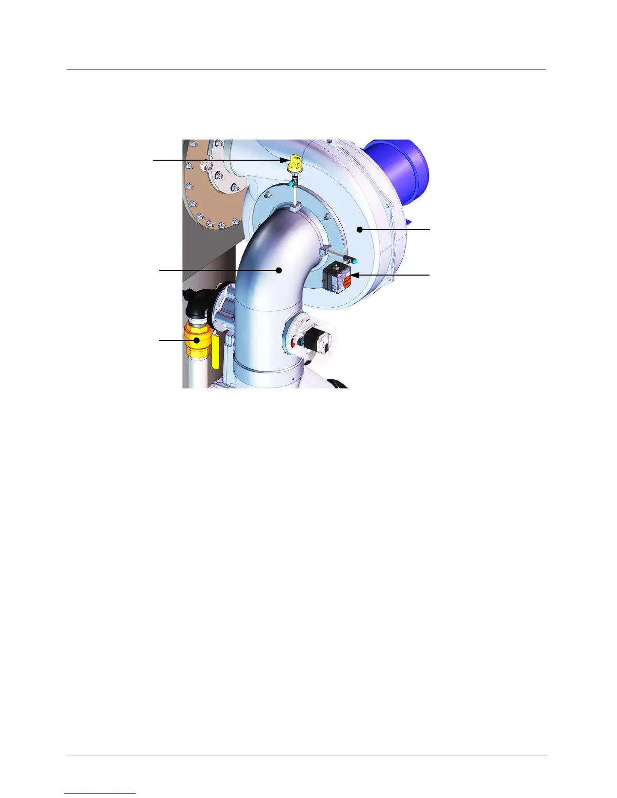
4. Next, the blower proof switch on the Air/Fuel Valve (Figure 3-5) closes. The display will
show Purging and indicate the elapsed time of the purge cycle in seconds.
Figure 3-5: Blower Proof Switch
NOTE
A Function Timing Chart for the BMK6000 Proved Pilot Control
System is provided in Figure 3-7, below.
5. Upon completion of the purge cycle, the Control Box initiates an ignition cycle and the
following events occur:
a) The Air/Fuel Valve rotates to the low-fire (Ignition Position) position and closes the
ignition switch. The Dial on the Air/Fuel Valve will read between 45 and 50 (Figure 3-6)
to indicate that the valve is in the low-fire position.
b) Power is supplied to the Spark Igniter.
c) Power is supplied to the Pilot Gas Solenoid.
d) The Optical Pilot Flame Sensor proves the Pilot Flame and the red LED stops
blinking and changes to steady ON.
e) Ignition relay 1 (R1) closes allowing the main Burner ignition sequence to start.
SWITCH
SWITCH