Benchmark 6000 Boiler Installation, Operation & Maintenance Manual
CHAPTER 3 – OPERATION
OMM-0086_0D AERCO International, Inc. • 100 Oritani Dr. • Blauvelt, NY 10913 Page 53 of 210
GF-133 Ph.: 800-526-0288 03/20/14
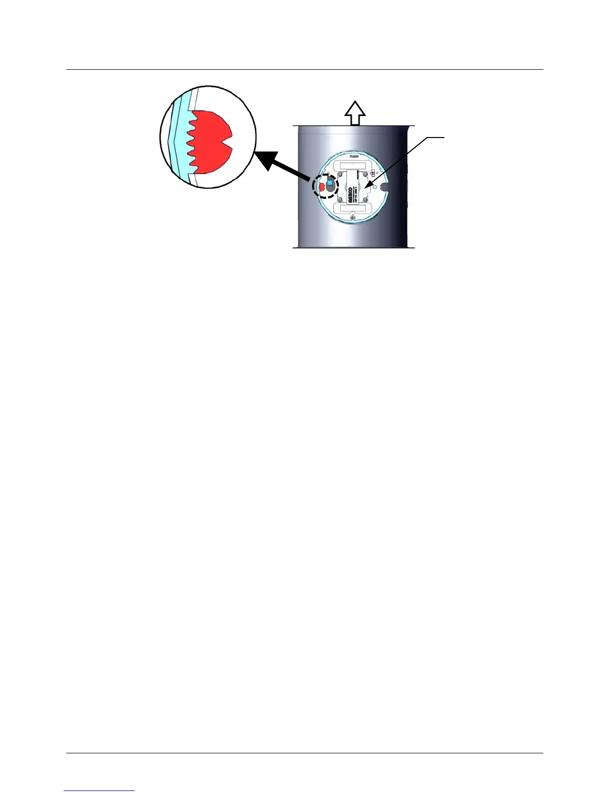
Figure 3-6: Air/Fuel Valve In Ignition Position
6. When ignition relay 1 (R1) closes, power is supplied to the SSOVs and the following events
occur:
f) The SSOVs open allowing gas to flow into the Air/Fuel Valve.
g) The Main Burner ignites.
h) Main Burner flame is sensed by the C-More Controller.
i) The Control Box turns off power to the ignition transformer and Pilot solenoid valve.
j) Relay 2 (R2) remains energized via the POC Normally Open (N.O.) contact of the
upstream SSOV actuator.
7. A maximum of 7 seconds are allowed for the entire ignition sequence, from applying power
to the ignition transformer through actual Burner flame establishment. The igniter relay will
be turned off one second after flame is detected.
8. After 2 seconds of continuous flame, Flame Proven will be displayed and the flame
strength will be indicated. After 5 seconds, the current date and time will be displayed in
place of the flame strength.
9. With the unit firing properly, it will be controlled by the temperature controller circuitry. The
boiler’s VALVE POSITION will be continuously displayed on the front panel bargraph.
Once the demand for heat has been satisfied, the C-More Controller will turn off the SSOV gas
valves. The blower relay will be deactivated and the Air/Fuel Valve will be closed. Standby will
be displayed.
MOTOR