EasyManua.ls Logo

Aerco BENCHMARK 6000 - Page 54

Aerco BENCHMARK 6000
210 pages
Print Icon
To Next Page IconTo Next Page
To Previous Page IconTo Previous Page
Loading...
Benchmark 6000 Boiler Installation, Operation & Maintenance Manual
CHAPTER 3 OPERATION
Page 54 of 210 AERCO International, Inc. 100 Oritani Dr. Blauvelt, NY 10913 OMM-0086_0D
03/20/14 Ph.: 800-526-0288 GF-133
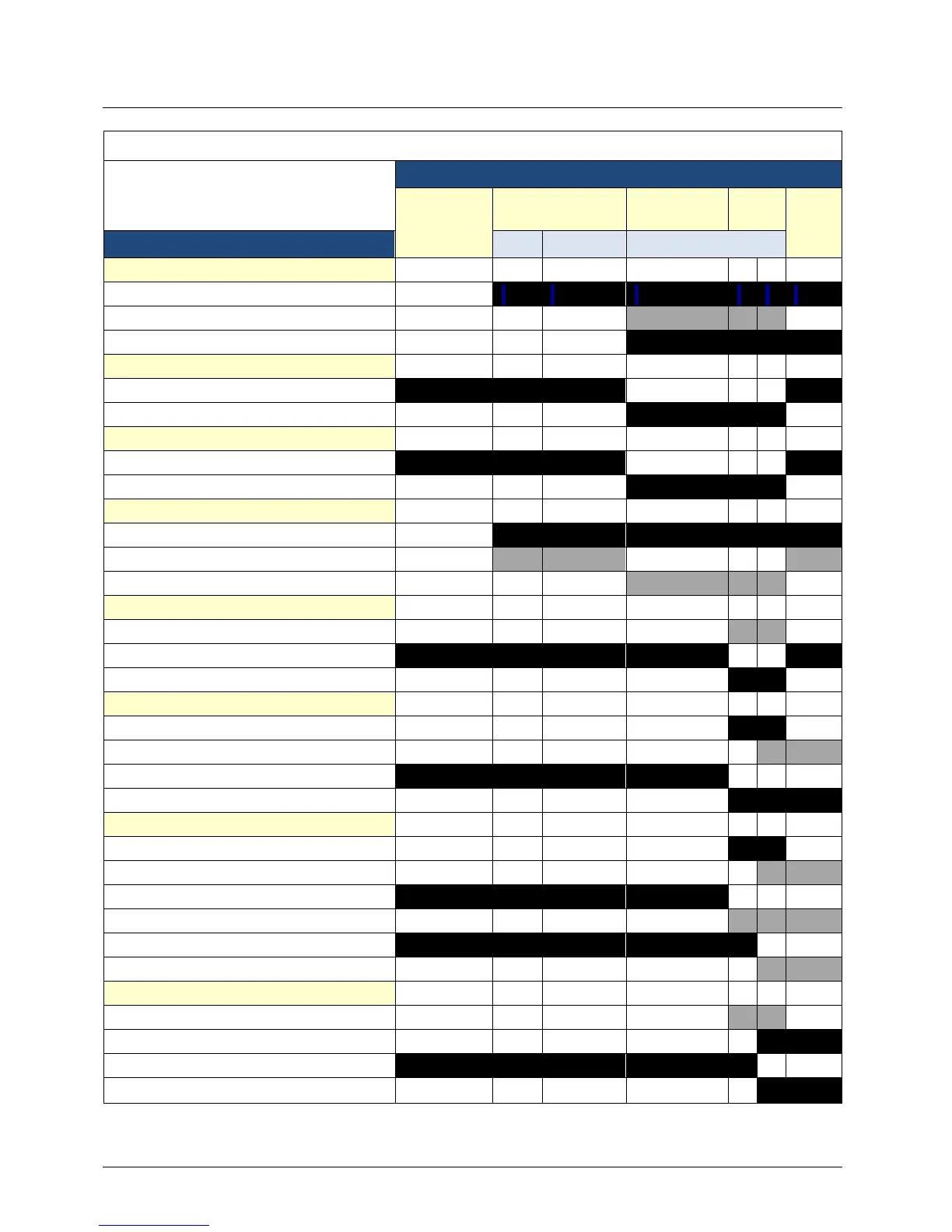
BMK 6000 Function Timing Chart For Proved Pilot Control System
OPERATING STATE
STANDBY
C-MORE
PRE-PURGE
PFEP MFEP
RUN
COMPONENT
T=0s 30≤T≤60s T= 7 sec
C-MORE CONTROL BOX
Scanner Power
Ignition Power
SSOV Power
PILOT VALVE
Pilot Valve Closed
Pilot Valve Open
IGNITION TRANSFORMER
Transformer Off
Transformer On
UV SCANNER
Powered
"Ignored"
In Use
RELAY 1 (R1)
Coil
C-NC
C-NO
RELAY 2 (R2)
Coil Power from R1
Coil Power from SKP 15 AUX
C-NC
C-NO
UPSTREAM SSOV (SKP15)
Power through R1
Power through R2 and AUX
POC C-NC
POC C-NO
AUX C-NC
AUX C-NO
DOWNSTREAM SSOV (SKP25)
Power through R1
Power through R2 and AUX
POC C-NC
POC C-NO
Figure 3-7: Timing Chart For Proved Pilot System

Table of Contents

Related product manuals