11
"INFO" MENU
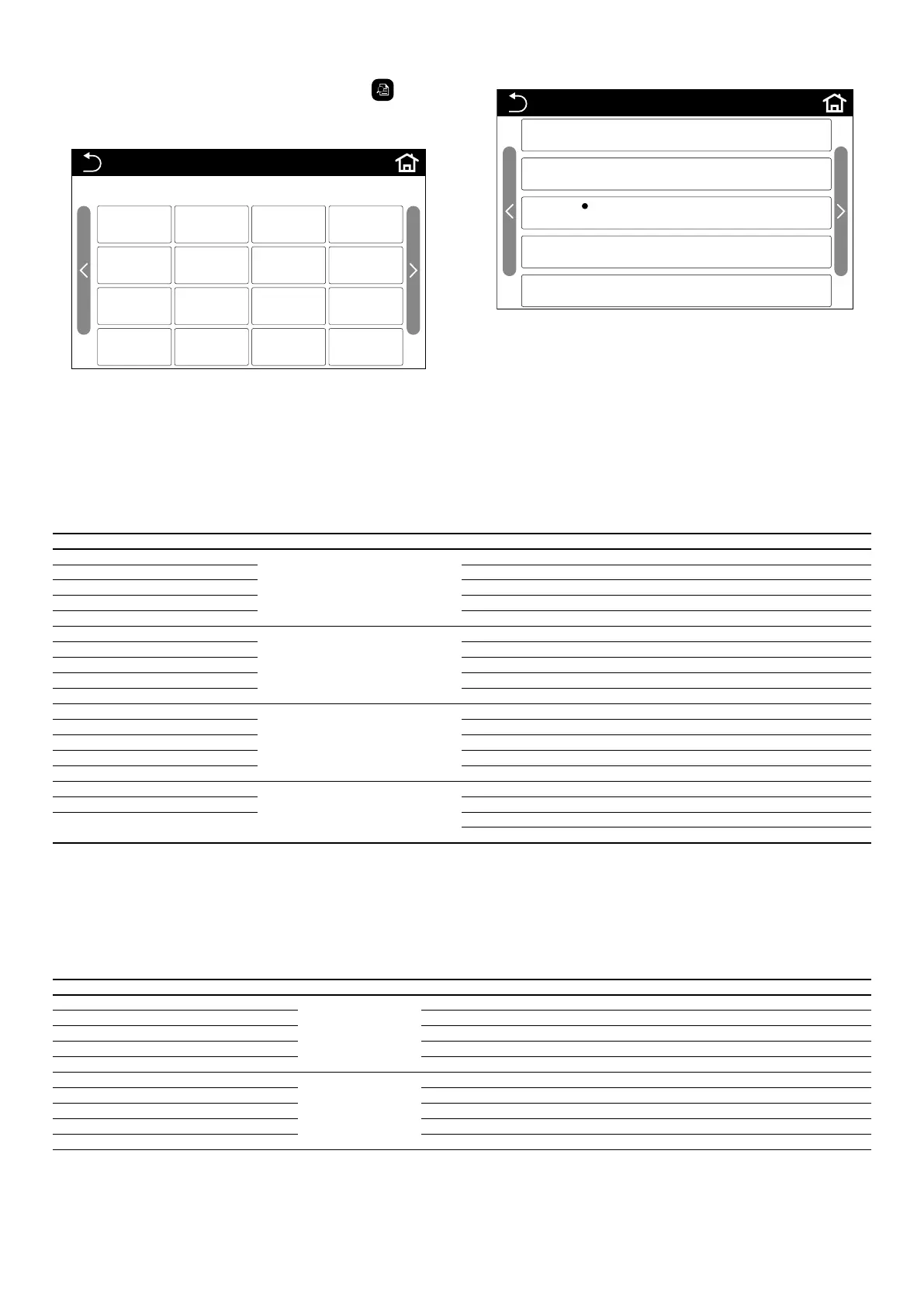
By pressing the "INFO." menu icon from the menu selection page ( ), it will be
possible to display information about the unit; this information is divided as shown
in the following gures:
INFO (1/1)
On-line units: 0
UNIT01 UNIT02 UNIT03 UNIT04
UNIT05 UNIT06 UNIT07 UNIT08
UNIT09 UNIT10 UNIT11 UNIT12
UNIT13 UNIT14 UNIT15 UNIT16
Note:
— If a unit is in alarm it will be reported in red, and a dot will appear to identify
them;
— the units currently connected and available will appear white;
— units that are oine and therefore not available will appear grey;
Once the reference unit has been selected, you will see a window where you can
choose the type of information to be visualised:
INFO-UNIT (1/1)
Status
Parameter
Error
Error record
Bar codes
Note:
— only the active units (shown in white) can be selected
— if a unit is in alarm, a dot will appear to identify it under the "Error" button;
(1) Status:
Pressing the "Status" button will take you to information about the current func-
tioning of the unit, which is divided into several pages; to navigate through the
pages you will need to use the arrow keys located on the right and left side of the
page;
Note: Information and values are in display-only mode;
Elements displayed in the “Status” menu
Name Available at the page Status
System status
1
O, Cooling, Heating, Defrosting, Automatic anti-free
Compressor 1 On, O
Compressor 2 On, O
Fan 1 On, O
Fan 2 On, O
Water pump 1
2
On, O
Water pump 2 On, O, Without
Flow switch Closed/Open
Four-way valve 1 On, O
Four-way valve 2 On, O
Electric heater 1
3
On, O
Electric heater 2 On, O
Contact-control On, O
Discharge T-sensor 1 Unlocked/Locked
Discharge T-sensor 2 Unlocked/Locked
Electromagnetic valve 1
4
On, O
Electromagnetic valve 2 On, O
Electric ball valves
N/A
On, O (*)
(*) For the HMG-P series
Note:
— if a parameter is not available for the unit, the letters "N/A" are shown
— if "Alternation function" is "O", the default value of "Water pump 2" will be
"Without"
— please note that the unit can manage up to two electric resistances via potential
free contact (for more information, refer to the unit's wiring diagram);
— "Electromagnetic valve" items refer to the solenoid valves upstream of the cap-
illary (refer to the unit's cooling diagrams for more information);
(2) Parameteri:
Press the "Parameter" button to access information about the unit parameters:
List of unit parameters
Operating parameter Available at the page Description
Entering water-T
1
Water temperature at heat exchanger input
Leaving water-T Water temperature at heat exchanger output
Defrosting temperature 1 Defrosting sensor 1 temperature
Defrosting temperature 2 Defrosting sensor 2 temperature
Discharge temperature 1 Compressor ow 1 temperature
Discharge temperature 2
2
Compressor ow 2 temperature
Anti-freezing-T Low water temperature limit (cold)
Anti-over-heating-T High water temperature limit (hot)
External air temperature External air temperature
Suction temperature 1 Compressor 1 intake temperature