Installation
Subject to Export Control, see Cover Page for details.
2-6
Accessory Connectors
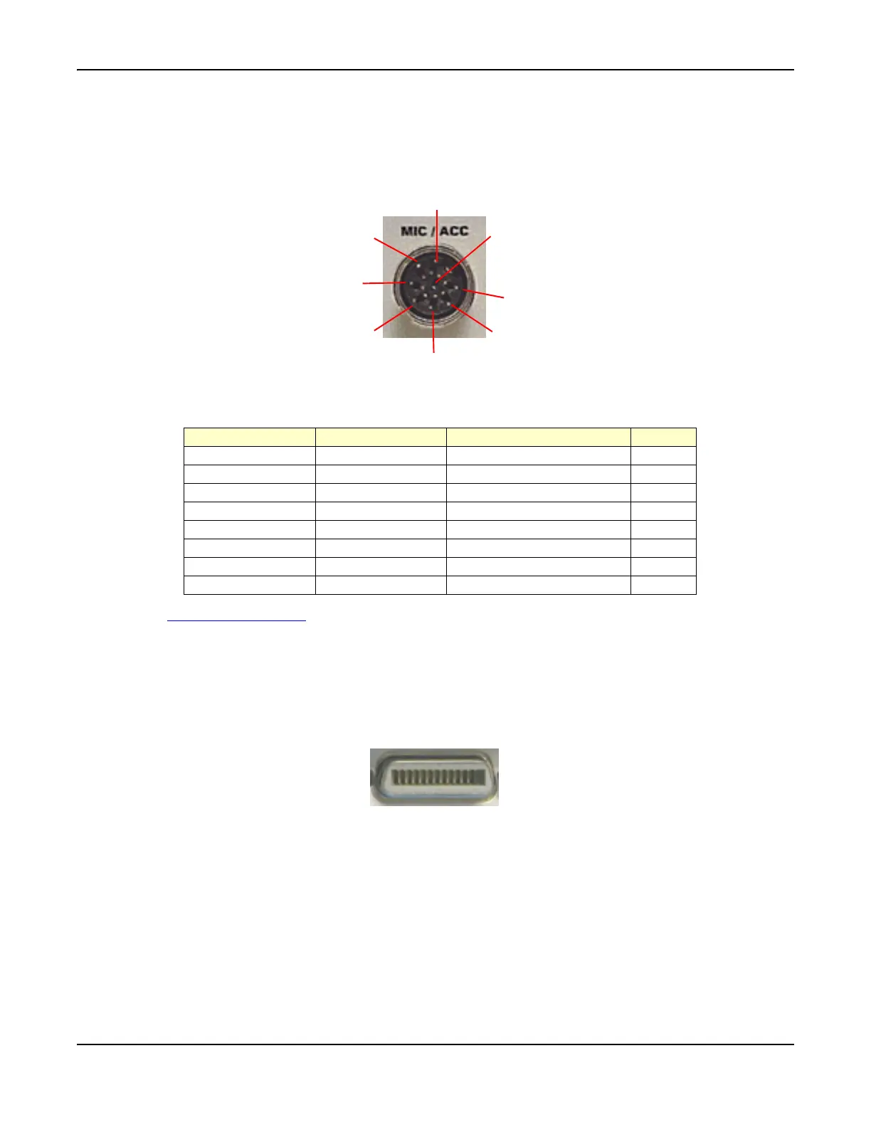
MIC/ACC Connector
The MIC/ACC Connector is an 8 pin DIN connection with ring-lock.
Fig. 2-5 MIC/ACC Pin Locations
MIC/ACC Connector pin functions are as follows:
See also MIC/ACC Connector in Chapter 3, Test Set Operation.
GPIB Connector
The GPIB Connector contains a standard socket mounted on the rear panel of the Test Set. Refer to
Fig. 2-6 for pin locations. The cable assemblies have male-female connectors at both ends to allow
devices to be interconnected in star or linear arrangements. Cable length restrictions for a network
are defined in the GPIB/IEEE 488/2 specification.
Fig. 2-6 GPIB Connector Pin Locations
8
6
1
4
2
5
3
7
Pin Number Signal Name Signal Type I/O
1 MIC Switch (PTT) TTL Out
2 MIC Audio Audio In
3 Demod Audio Audio Out
4 No Connection
5 10-15 Vdc, 500 mA
6 No Connection
7 MIC Switch (PTT) TTL In
8 GND Instrument ground
1
12
13 24