Installation
Subject to Export Control, see Cover Page for details.
2-10
PS/2 Interface Connectors
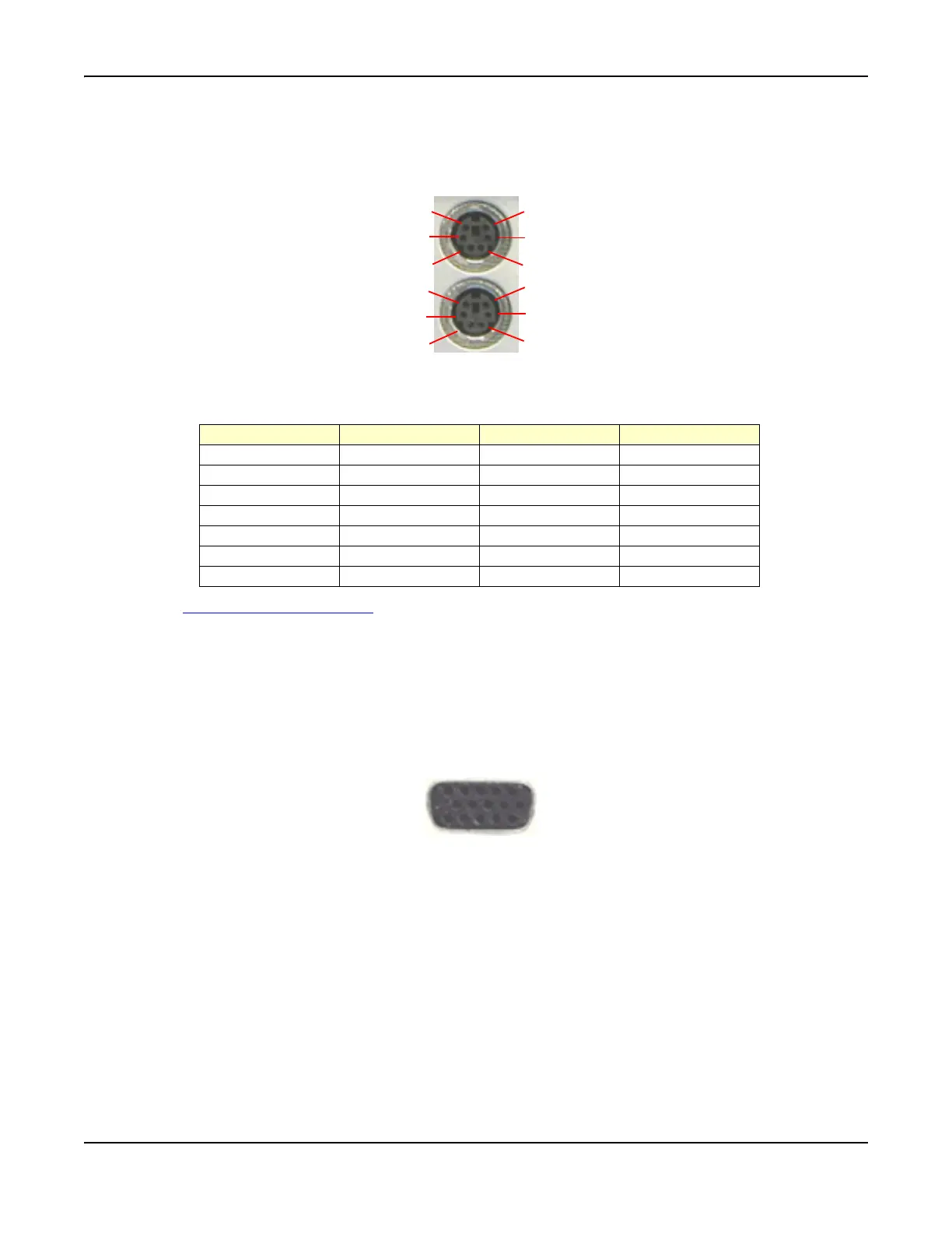
The pin-outs for the dual PS/2 mouse and keyboard connectors are shown in Fig. 2-11. The
keyboard can only be connected to the lower PS/2 connector.
Fig. 2-11 PS/2 Connector Pin Locations
PS/2 Pin-Out Connector
See also PS/2 Interface Connector
in Chapter 3, Test Set Operation.
Test Connector
The Test Connector on the front panel is used for programming radios through a data connection.
The Test Connector consists of 4 digital input and 4 digital output (open collector) lines. The
Connector also provides a 0 to 12 V, 50 mA, programmable source. Refer to Fig. 2-12 for pin
locations.
Software to support specific radios is planned for future software releases.
Fig. 2-12 Test Connector Pin Locations
1
2
3
4
5
6
1
2
3
4
5
6
Pin Number Signal Type Signal Name Description
1 Bi-directional DATA Data
2 No Connection
3PowerGNDGND
4 Power +5 V Supply Voltage
5 Bi-directional CLK Clock
6 No Connection
Shell Earth Ground Chassis Ground
15
6
10
11
15