119
Chapter 6: Replacing Assemblies
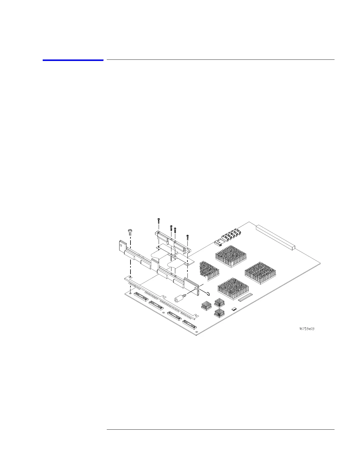
To replace the circuit board
1 Remove the logic analyzer cables using the “To remove the logic analyzer
cable” procedure on page 115.
2 Remove the four screws attaching the ground spring and back panel to the
circuit board, then remove the back panel and the ground spring.
3 Replace the faulty circuit board with a new circuit board. On the faulty
board, make sure the 2x15 (30-pin) ribbon cable is connected between J15
and J12.
4 Position the ground spring and back panel on the back edge of the
replacement circuit board. Install four screws to connect the back panel
and ground spring to the circuit board.
5 Install the logic analyzer cables using the procedure “To install the logic
analyzer cable” on page 117.
Artisan Technology Group - Quality Instrumentation ... Guaranteed | (888) 88-SOURCE | www.artisantg.com