34410A/11A User’s Guide 49
Features and Functions 2
Advanced Configuration Options
Power-On State
At power–on, the multimeter displays all segments of the two–line display
and all annunciators, for a period of several seconds, then changes to the
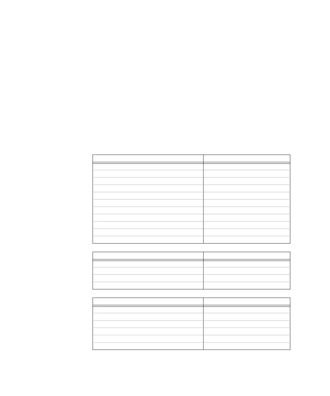
default display mode. The following tables show the state of multimeter
parameters at power on. Parameters marked with a bullet (
●) are stored
in non–volatile memory, and are not affected by power–on or a system
reset. For those parameters, the initial factory settings are shown. All
other parameters are stored in volatile memory, and are reset to the
indicated values at power–on, after a front–panel Reset command, or after
a *RST or SYSTem:PRESet command is issued from the remote interface.
Measurement Configuration Factory Setting
Function DC Volts
Range Autorange (for all functions)
*
Resolution 6.5 digits (0.3 ppm x Range) *
Integration Time NPLC on, 1 PLC *
Autozero On *
Aperture Off, 1 second *
● Input Impedance ● 10 MW (fixed for all VDC ranges)
AC Input Filter (bandwidth) 20 Hz (medium filter)
Nulls (for individual measurement functions) Off, 0 for all measurement functions
Second Display Off
*for all dc measurements
Math Operations Factory Setting
Math State Off
Math Registers Cleared (all registers)
dB relative value 0
dBm reference resistance 600W
Triggering Operations Factory Setting
Trigger Count 1
Trigger Source Immediate
Trigger Delay Auto Delay
Sample Count 1
Sample Source Auto
Sample Timer 1 second
 Loading...