CAUTION
Before replacing any high-voltage power supply, be sure to disconnect the
power cord to the laser head.
i. Record the laser tube current in the "ADJUSTMENT RECORD" located at the end of this section.
j. Turn off the system power supplies, disconnect the probe, set the TEST-NORM switch to NORM, and
reinstall the laser head covers.
k. Return all A3 jumpers moved in step 5-20(d) back to NRM position (left-most position).
Instrument Model Number: HP 5517B Page of Instrument Serial
Number: A
HP 5517B LASER HEAD ADJUSTMENT RECORD
Laser Output
Power
V
set
Laser Tube
Current
>180 µW
V
set
(Calculated) 3.5
mA ±0.1 mA
Laser Output
Power
V
set
Laser Tube
Current
>180 µW
V
set
(Calculated) 3.5
mA ±0.1 mA
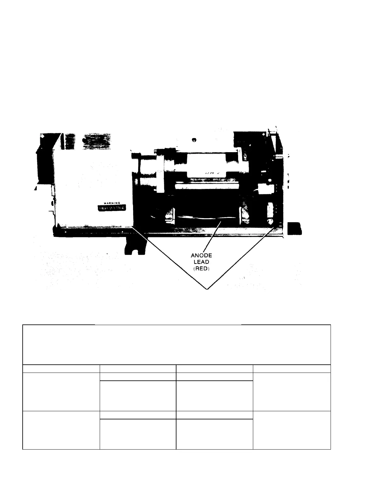
Figure 5-2. 5517B High Voltage Area and Anode
Lead

 Loading...


