58-1
CHANGE 1
To backdate 5517B Laser Heads from Series 3014A, make the following changes:
Page 6-5, Table 6-3. HP 5517B Board Assemblies Replaceable Parts (Continued)
Change A2 Power Supply part number from 0950-0470 to 05518-60303 for the 5517B.
NOTE
POWER SUPPLY PART NUMBER 0950-0470 HAS THREE INPUT WIRES. POWER SUPPLY PART NUMBER
05518-60303 HAS TWO INPUT WIRES. THE ORANGE WIRE WENT FROM THE POWER SUPPLY TO A1J3 PIN
2.
Page 6-10, Table 6-3. 5517B/C Miscellaneous Chassis Parts:
Change MP3 FRONT PANEL from 05517-20207 to 05517-20202. Change MP4 REAR PANEL from 05517-20208 to
05517-20204. Change MP8 LEFT COVER from 05501-00010 to 05517-00003. Change MP9 RIGHT COVER from
05517-60205 to 05517-60202.
CHANGE 2
A1 Connector boards with Date Code above 90232 do not include S1 and S2 cover interlock switches. For A1
Connector Boards with S1 and S2 interlock switches, make the following changes:
Table 1-1,
HP 5517B Laser Head Specifications and Performance Characteristics: Delete Step 2
under Safety Features.
Paragraph 5-3/5-4. SAFETY CONSIDERATIONS: Add the following:
NOTE
THE HIGH VOLTAGE POWER SUPPLY, A2, IS DISCONNECTED AUTOMATICALLY BY A1S1, WHEN THE HP
5517B/C COVERS ARE REMOVED. FOR ADJUSTMENTS AND SERVICING PURPOSES, THE HIGH VOLTAGE
SUPPLY CAN BE RE-ENABLED BY SETTING THE TEST-NORM SWITCH, A1S2, TO TEST AFTER THE HP
5517B COVERS ARE REMOVED.
Paragraph 5-14/5-15. Preliminary Procedure Add step b
and
Figure 7-1:
b. Check that the TEST-NORM switch (A1S2) located on the A1 Connector Board is set to NORM. See
Figure 7-1.
Paragraph 5-20. Add Step c:
c. On the A1 Connector Board, set TEST-NORM (A1S2) switch to TEST. See
Figure 7-1.
Change step k to read as follows:
k. Turn off the system power supplies, disconnect the probe, set the TEST-NORM switch to NORM, and reinstall
the laser head covers.
Page 6-4, Table 6-3. A1 Connector Board Replaceable Parts:
Add A1S1, 3101-2878, SWITCH PUSHBUTTON DPDTMOM .5 60 VAC/VDC. Add A1S2, 3101-2334, SWITCH
SLIDE DPDT SUBMIN .5A 125VAC/DC PC.
Paragraph 8-14, Safety Considerations: Add the following NOTE:
NOTE
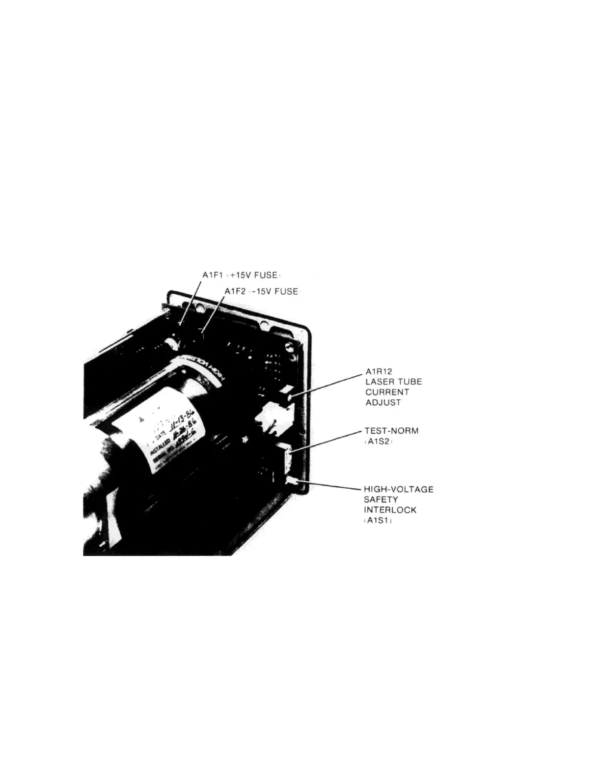
Figure 7-1. A1 Connector Board TEST-NORM Switch and Adjustment Locations

 Loading...


