7-3
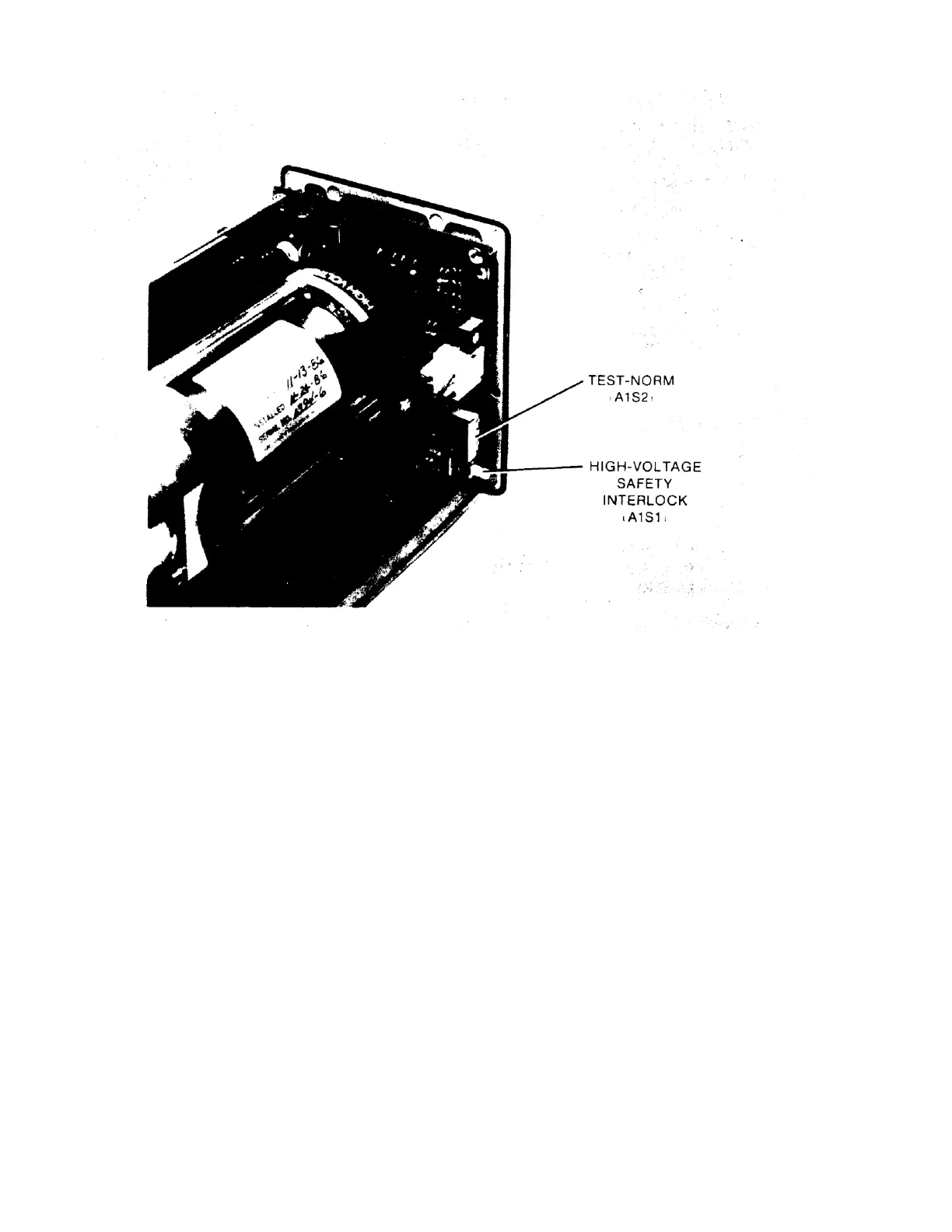
Figure 7-2. HP 5517B TEST-NORM Switch A1S2
Change paragraph 8-74, d, to read as follows:
d. Disconnect power and remove the covers of the HP 5517B. Set A1S2 to TEST and verify that all boards are seated
correctly and all test jumpers on the A3 board are in the left-most position (NRM).
Add WARNING after step 8-74, e:
WARNING
WITH A1S2 IN THE TEST POSITION, THE HP 5517B HIGH VOLTAGE POWER
SUPPLY IS ENABLED.
Paragraph 8-77.
Change paragraph 8-77 to read as follows:
8-77. Capacitors A1C1 through A1C3 serve to filter out noise on the ±15 Volt power supply lines. A1C4
filters current spikes created by the high voltage power supply. Diode A1CR1 provides reverse voltage
protection and A1CR2 protects against electrical transients. A1S1 is asafety interlock which removes
power from the laser power supply when the HP 5517B covers are removed. Switch A1S2 bypasses the
interlock so that the HP 5517B can be serviced. A1S1 and A1S2 are wired in such a way that the
interlock must be enabled before replacing the cover. Fuses A1F1 and A1F2 protect the system against
laser power supply failures. A1J4 is the connector for the laser tube heater and cathode. A1 DS5 and
A1DS6, +15V POWER ON and -15V POWER ON LEDs respectively, turn on when the power cable is
connected to POWER connector A1J2. A1 DS8 (LASER ON LED) lights when the high voltage supply is

 Loading...


