Setting Up Generic and Advanced Signals Setting Up Signals for a Stressed Eye Diagram Measurement
58 Agilent 81133A/81134A Pulse Generator User’s Guide, August 2002
Setting Up Signals for a Stressed
Eye Diagram Measurement
Tas k Set up signals for a stressed eye measurement by:
• Intentionally adding jitter to your signals
• Changing the crossover of the eye pattern
One-Channel Setup For a one-channel setup, you need:
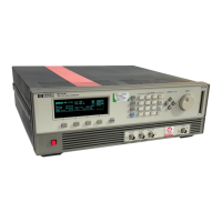
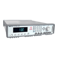
• An 81133A or 81134A instrument
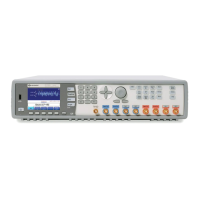
• An arbitrary waveform generator to generate additional jitter, for
example, the 33250A
• A scope for displaying the signals, for example, the 86100 DCA
Two-Channel Setup For a two-channel setup, you need:
• An 81134A instrument
• An arbitrary waveform generator to generate additional jitter, for
example, the 33250A (you might need two of them for two
“independently jittering” output signals)
• A scope for displaying the signals, e.g. the 86100 DCA
NOTE This example is demonstrated with the 81134A instrument. The
two-channel instrument allows you to generate the distorted eye and a
clean “reference eye” at the same time.
Use Cases Stressed eye measurements can be used:
• In board design: For testing the RF behavior of different board
materials and transmission line geometries.
• For testing cables and connectors.
• For testing A/D converters.