Setting Up Generic and Advanced Signals Setting Up Signals for a Stressed Eye Diagram Measurement
64 Agilent 81133A/81134A Pulse Generator User’s Guide, August 2002
Play with the Settings
The delay control input adds additional delay to the signal depending
on the voltage that is fed to the input.
• On the 33250A, you can change the amplitude and frequency of the
signal to show the influence of the delay control input.
• Change from sine wave to rectangular wave by pressing the
corresponding button.
You can also change the variable crossover point on the 81134A
Channel panel.
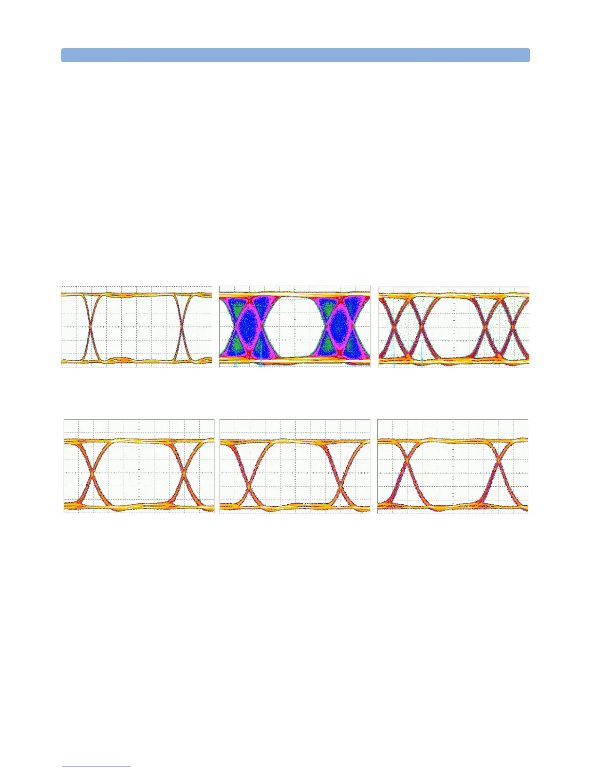
The following signals show a clear eye, a signal modulated with sine
wave and a signal modulated with rectangular wave.
Clear Eye Delay modulated with sine
wave
Delay modulated with
rectangle wave
50 % Variable Crossover 30 % Variable Crossover 70 % Variable Crossover