Chapter 3 Calibration Procedures
Measurement Techniques
50
General Measurement Techniques
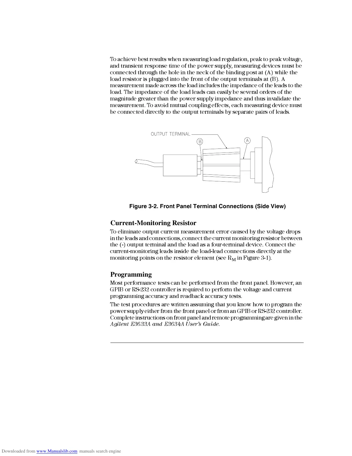
T o achieve best results when measuring load regulation, peak to peak voltage,
and transient response tim e of the power supp ly, meas urin g devices must be
connected through the hole in the neck of the binding post at (A) while the
load resisto r is plugged into the front of the output terminal s at (B). A
measurement made across the load includes the impedance of the leads to the
load. The impedance of the load leads can easily be several orders of the
magnitude greater than the power suppl y impedance and thus invalid ate th e
measurement. T o avoid mutual coupling effects, each measuring device must
be connected directly to the output terminals by separate pairs of leads.
Figure 3-2. Front Panel Terminal Connections (Side View)
Current-Monitoring Resistor
To eli m inate output current measurement error caused by th e voltage dr ops
in the leads and connections, connect the current monitoring resistor between
the (-) output terminal and the load as a four-terminal device. C onnect the
current-monitoring leads inside the load-lead connections directly at the
monitoring points on the resistor element (see R
M
in Figure 3-1).
Programming
Most performance tests can be performed from the front panel. However, an
GPIB or RS-232 controller is required to perform the voltage and curr ent
programming accuracy and readback accuracy tests.
The test procedures are written assuming that you know how to program the
power supply either from the front panel or from an GPIB or RS-232 controller.
Complete instructions on front panel and remote programming are given in the
Agile nt E36 33A and E3 634A User ’s Guide
.

 Loading...


