Chapter 3 Calibration Procedures
Constant Voltage (CV) Verifications
55
3
Load Transient Response Time
This test measures the time for the output voltage to recover to within 15 mV
of nom inal output voltage following a load change from full load to half load,
or half load to full load.
1
Turn off the power supply and connect the output to be tested as shown in
Figure 3-1 with an oscilloscope. Operate the electronic load in constant current
mode.
2
Turn on the power supply. Select 20V/10A* or 50V/4A** range, enable the
output, and set the display to the limit mode. When the display i s in the limit
mode, program the current to the full rated value (10.0 A)* or (4.0 A)** and the
voltage to the full rated value (20.0 V)* or (50.0 V)**.
3
Set the electronic load to transient operation mode between one half of the
output’s full rated value and the output’s full rated value at a 1 kHz rate with
50% duty cycle.
4
Set the oscilloscope for ac coupli ng, internal sync, and lock on either the
positive or negative load transient.
5
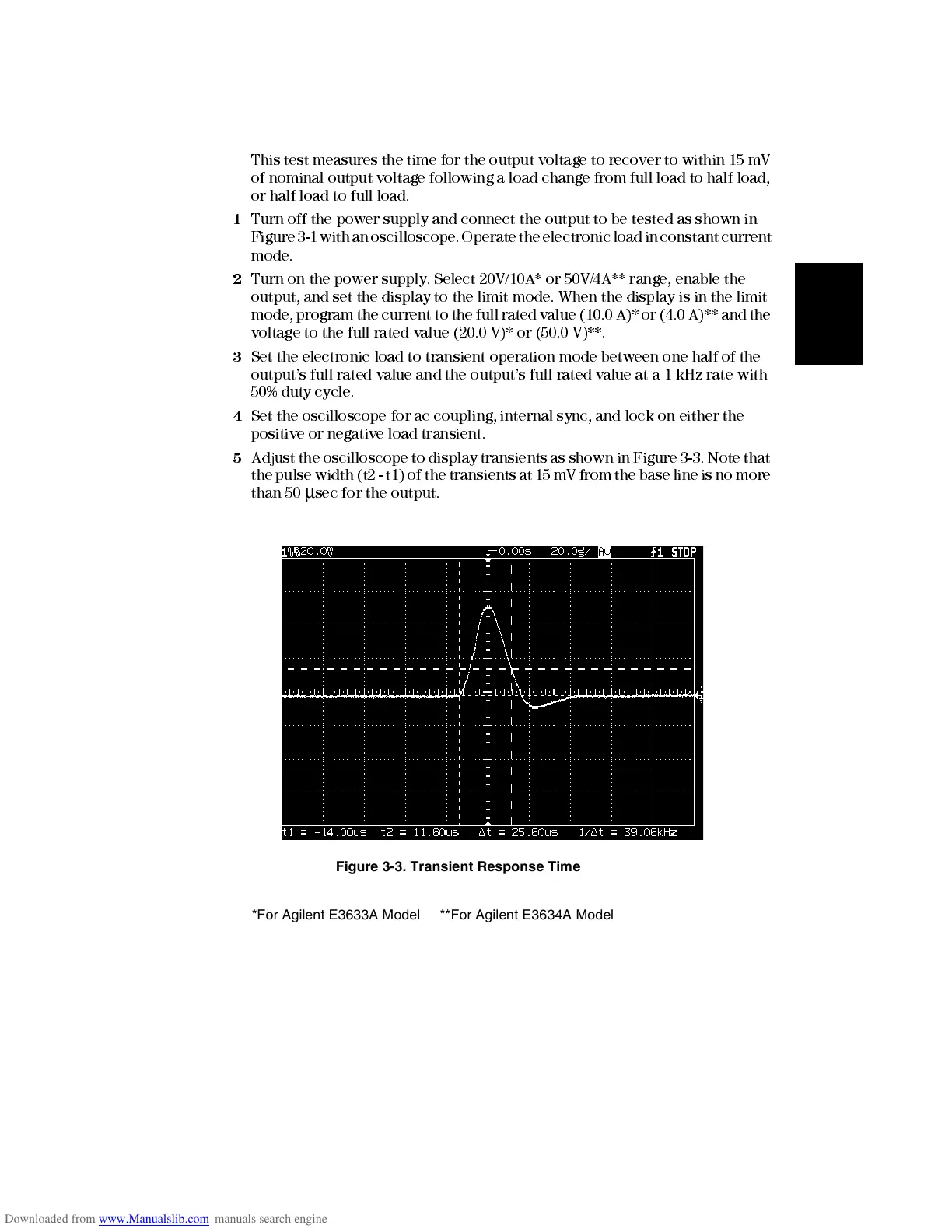
Adjust the oscilloscope to display transients as shown in Figure 3-3. Note that
the pulse width (t2 - t1) of the t ra nsients at 15 mV from the base line is no more
than 50
μ
sec for the output.
Figure 3-3. Transient Response Time
*For Agilent E3633A Model **For Agilent E3634A Model

 Loading...


