4-14 Service Guide E8364-90026
Troubleshooting PNA Series Microwave Network Analyzers
Power Up Troubleshooting E8362B, E8363B, E8364B
6. Connect the display ribbon cable and display lamp cable from A2 to A3. Connect the
front panel interface ribbon cable coming from the analyzer to the A3 board.
7. Turn the analyzer on and refer to “Verifying the Inverter Board” on page 4-14 and
“Verifying the A3 Front Panel Interface Board” on page 4-16 to test and troubleshoot
the boards.
Verifying the Inverter Board
WARNING
High voltage is present on the inverter board and the A3 front panel
interface board. Be careful when measuring signals and voltages on
these boards.
1. To access the front panel boards for measurements, it is necessary to remove the front
panel assembly. Refer to “Removing and Replacing the Front Panel Assembly” on
page 7-10.
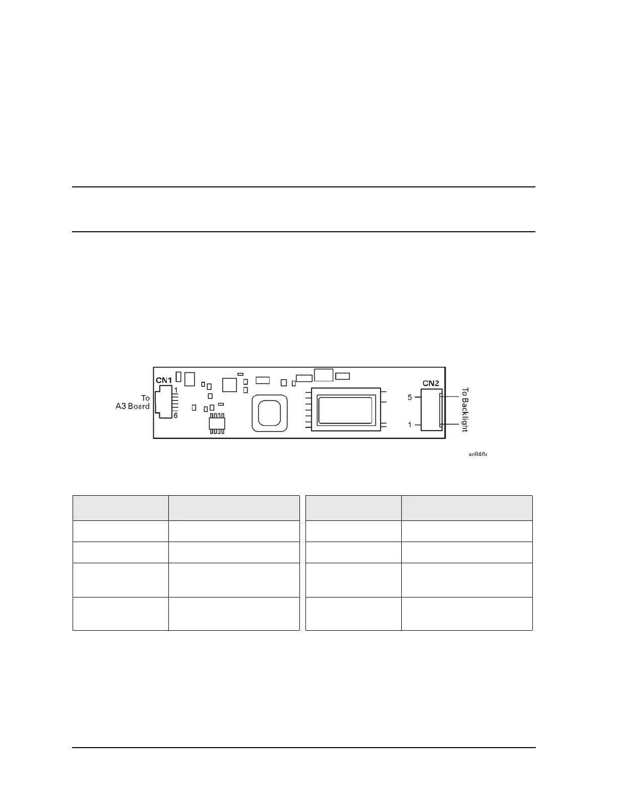
Using Figure 4-5 as a reference, measure the signals and voltages indicated in Table 4-3 on
page 4-14. If the signals and voltages measure good, the inverter board is functioning
correctly.
Figure 4-5 Inverter Board Test Point Locations
After measuring the points CN1 and CN2, match the results and perform the rework as
indicated in the action column in Table 4-4.
Table 4-3 Inverter Board, Voltages and Signals
Test Point Signal or Voltage Tes t Point Signal or Voltage
CN1 pin 1 +5.1 Vdc CN1 pin 5 0 V (ground)
CN1 pin 2 +5.1 Vdc CN1 pin 6 +2.54 V
CN1 pin 3 39 mV CN2 pin 1
+400 V peak sinewave
@ 38 kHz
CN1 pin 4 0 V (ground) CN2 pin 5
ac neutral
(referenced to pin 1)