1 Quick Reference
10 Series N8700 User’s Guide
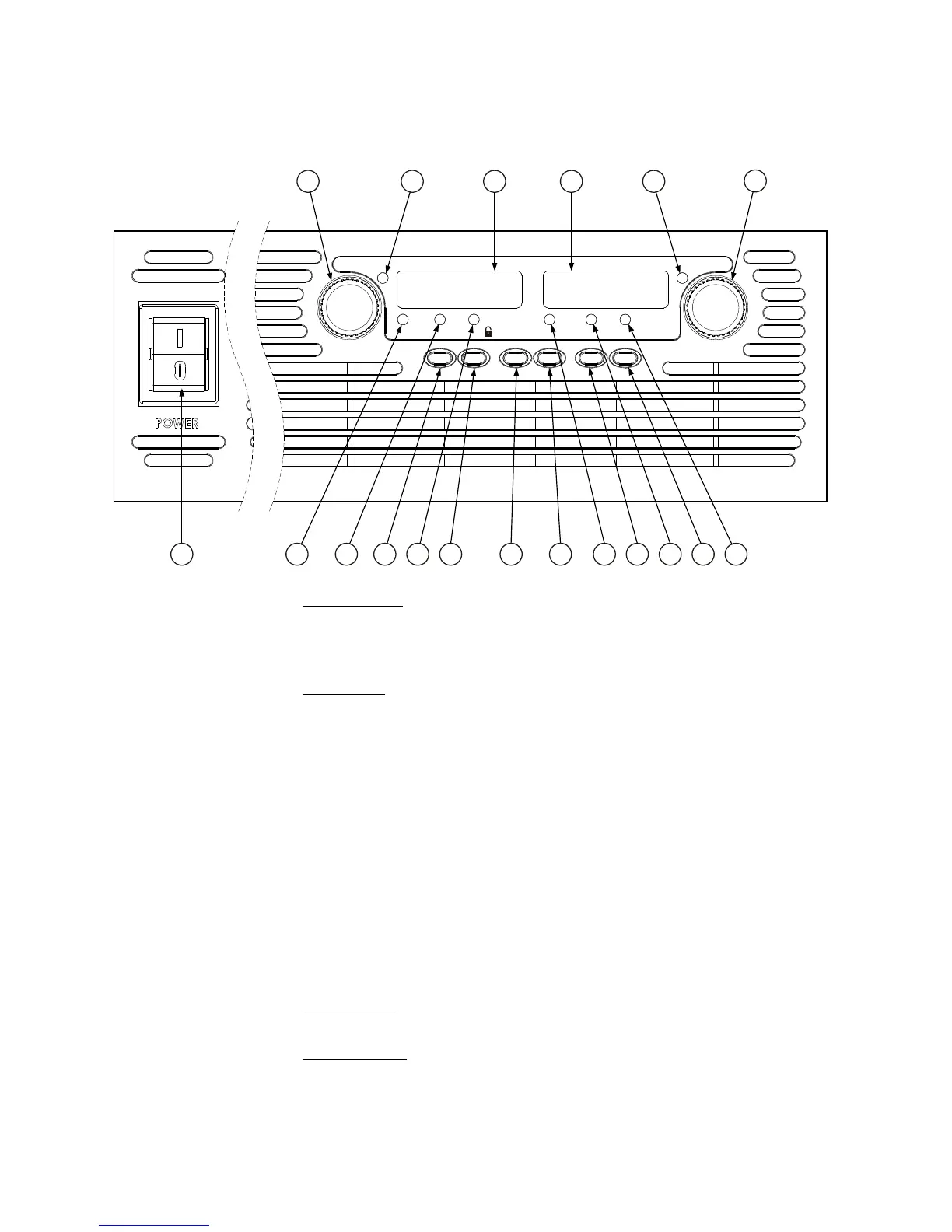
The Front Panel - At a Glance
1 – VOLTAGE knob
Voltage function: Adjusts the output voltage, the over-voltage protection level, and the
under-voltage limit. If over-voltage protection or under-voltage limits have been set,
you cannot program the output voltage outside those limits. Press the FINE button to
set fine adjustment resolution.
GPIB address: Selects the GPIB address when OCP/488 is pressed and held.
2 – VOLTAGE indicator Indicates the unit is in constant voltage mode – with the output voltage held constant.
3 – DC VOLTS display Normally displays the voltage measured at the sense terminals.
- Indicates the programmed voltage setting when the LIMIT button is pressed.
- Indicates either the OVP or UVL setting when the OVP/UVL button is pressed.
- Indicates the GPIB address when the OCP/488 button is pressed and held.
- Indicates the IP and Ethernet address when the LAN button is pressed and held.
4 – DC AMPS display Normally displays the current measured at the output terminals.
- Indicates the programmed current setting when the LIMIT button is pressed.
- Indicates the IP and Ethernet address when the LAN button is pressed and held.
5 – CURRENT indicator Indicates the unit is in constant current mode – with the output current held constant.
6 – CURRENT knob Adjusts the output current.
Press the FINE button to set fine adjustment resolution.
7 – OUT ON indicator Indicates the output is enabled or on.
8 – OUT ON button
Output function: Press the OUT ON button to turn the output on or off. Press the OUT
ON button to reset the unit and return the output to on after an OVP or OCP event.
Start-Up function: Press and hold the OUT ON button to toggle between the Safe-Start
and Auto-Restart modes. The display cycles between SAF and AU7. Releasing the OUT
ON button while one of the modes is displayed selects that mode.
1
CV CC
VOLTAGE DC VOLTS DC AMPS CURRENT
PROT FINE LIMIT/ UVL OCP/488 LAN OUT ON
OVP
2 3 4 5
6
78
9101112
1314
1516171819