1 Quick Reference
12 Series N8700 User’s Guide
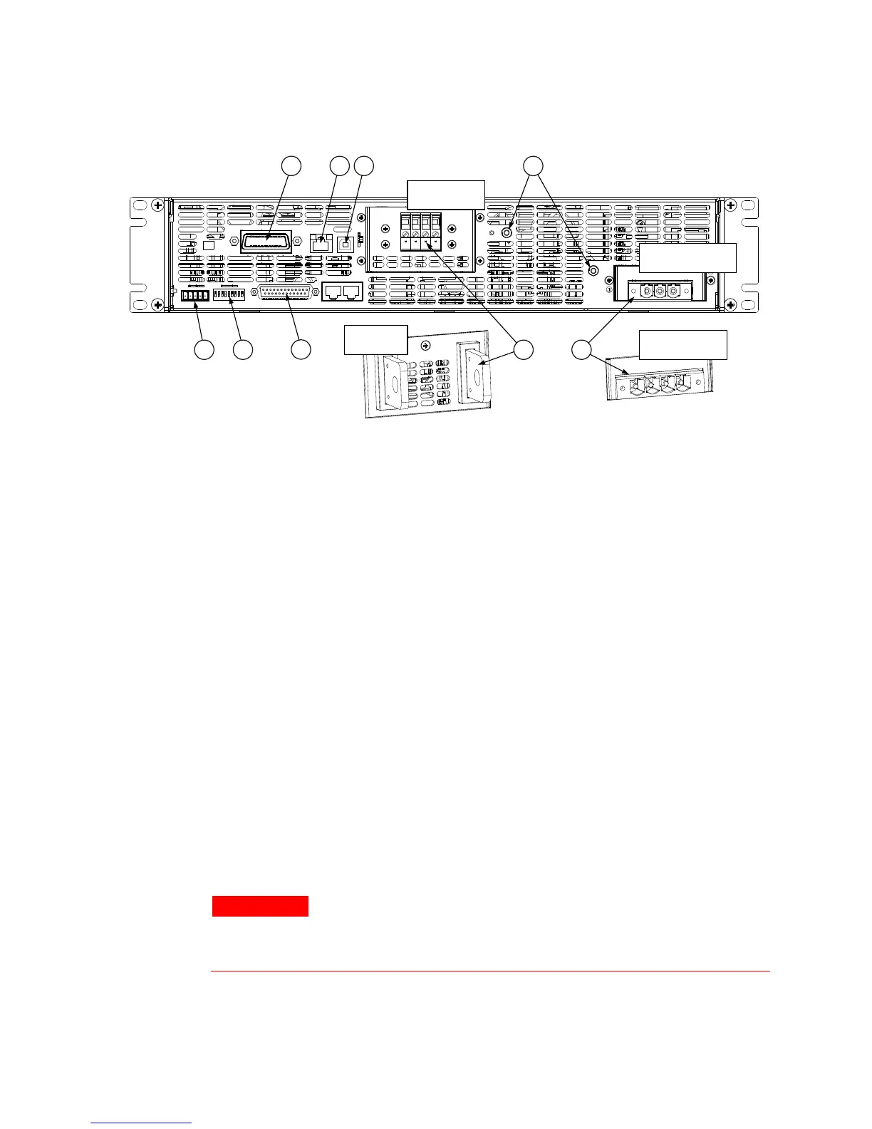
The Rear Panel – At a Glance
1 – AC input connector Header with mating plug-in connector for both the 3.3 kW and 5 kW output models.
A 3-conductor plug is provided for single-phase VAC.
A 4-conductor plug is provided for 3-phase VAC.
2 – DC output connector Wire clamp connector is used for 150V, 300V and 600V models.
Bus bars are used for 8V to 100V models.
3 – Analog
programming
connector
Connector for the analog interface. Includes output voltage and current limit
programming and monitoring signals, Shut-Off control (electrical signal),
Enable/Disable control (dry-contact), power supply ok (Power Supply OK) signal and
operation mode (CV/CC) signal. (See next page for details)
4 – SW1 setup switch Nine-position switch for selecting remote programming and monitoring modes for
Output Voltage, Current Limit and other control functions. (See next page for details)
5 – Remote Sense
connector
Connector for making remote sensing connections for regulating the load voltage and
compensating for wiring voltage drop. (See next page for details)
6 – GPIB connector Connector for connecting to a GPIB interface. See chapter 4 for setup.
7 – LAN connector Connector for connecting to a LAN interface. LINK LED indicates link integrity. TX LED
indicates LAN activity. See chapter 4 for LAN setup.
8 – USB connector Connector for connecting to a USB interface. See chapter 4 for setup.
9 – Ground screw & nut M4x8 screws with nut for making chassis ground connections
WARNING
SHOCK HAZARD The AC power cable provides a chassis ground through the
ground conductor. Be certain that your power source is three-conductor for
single-phase models or four-conductor for 3-phase models with the ground
conductor (green/yellow) connected to earth ground.
1
6
7
8
5
4
3
9
2
8V – 100V
(bus bar)
150V – 600V
(wire clamp)
3-phase VAC
(four-conductor)
2-phase VAC
(three-conductor)