2 Installation
24 Series N8700 User’s Guide
Along with conductor temperature, you must also consider voltage
drop when selecting wire sizes. Although the power supply will
compensate for up to 5 volts in each load wire, it is recommended to
minimize the voltage drop to less than 1 volt to prevent excessive
output power consumption from the power supply and poor dynamic
response to load changes.
Load Connections for 8V to 100V Models
WARNING
SHOCK HAZARD Hazardous voltages may exist at the outputs and the load
connections when using a power supply with a rated output greater than 40V.
To protect personnel against accidental contact with hazardous voltages,
ensure that the load and its connections have no accessible live parts. Ensure
that the load wiring insulation rating is greater than or equal to the maximum
output voltage of the power supply.
CAUTION
Ensure that the load wiring mounting hardware does not short the output
terminals. Heavy connecting cables must have some form of strain relief to
prevent loosening the connections or bending the bus-bars.
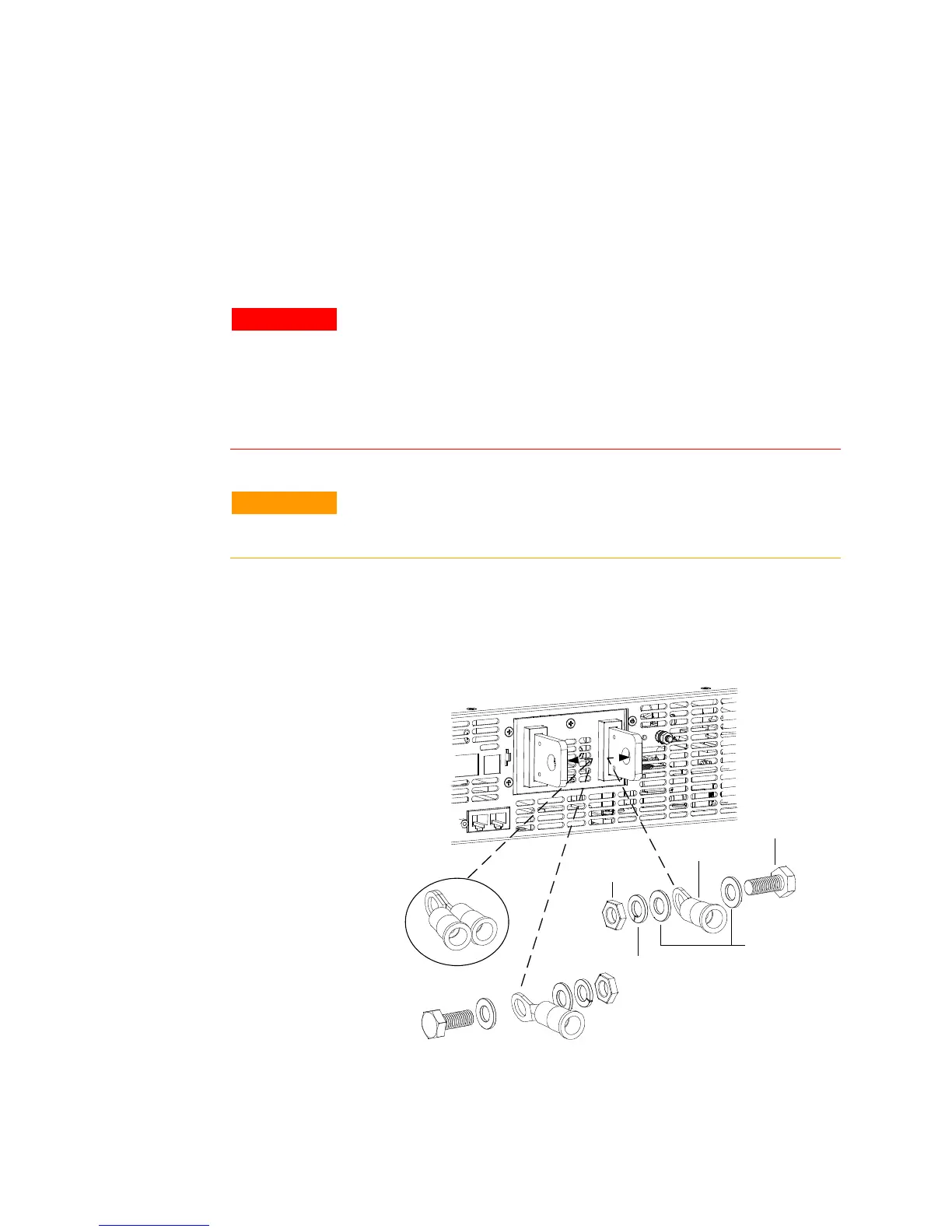
1 As shown in the following figure all load wires should be
properly terminated with wire terminal lugs securely attached.
DO NOT use unterminated wires for load connections at the
power supply. Attach the wire terminals to the inside of the bus-
bars to ensure enough space for installing the shield.
2 Install the shield after you have finished connecting the load
wires. Route the load wires through the openings in the back of
the shield. If necessary, use diagonal cutters and remove the
Flat
washers
M10 x 25
bolt
Wire Lug
Hex nut
Spring
washer
Paralleled
wire lugs