2 Installation
26 Series N8700 User’s Guide
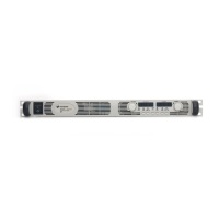
Connect load wires to the power supply output wire clamp connector
as follows:
1 Strip wires back approximately 10 mm (0.4 in).
2 Loosen the connector terminal screws and insert the stripped
wires into the terminal. Tighten the terminal screws securely.
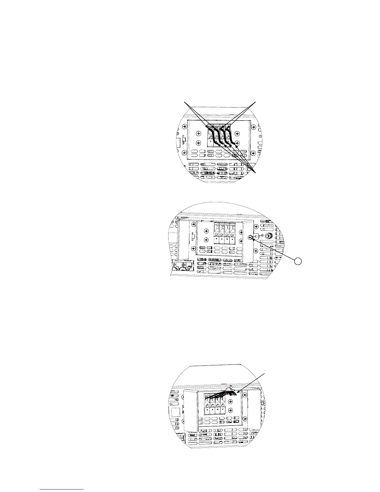
3 Loosen the chassis screw marked A and remove (save).
4 Slide the slotted tab on the protective shield’s left side into the
chassis slot and lock into place. Insert the right side shield screw
A (previously removed) to fix the shield to the chassis. Screw
tightening torque: 4.8 - 5.3 in-lb (0.54 - 0.6 Nm).
5 Route the load wires to the tab at the top of the shield. Ensure
the wire length inside the shield is long enough to provide proper
strain relief.
6 Attach the load wires to the notched shield tab using a tie-wrap
or equivalent as shown in the following figure.
Load wires
Negative
(-) output
Positive
(+) output
 Loading...