Getting Started 1
U2000 Series Operating and Service Guide 3
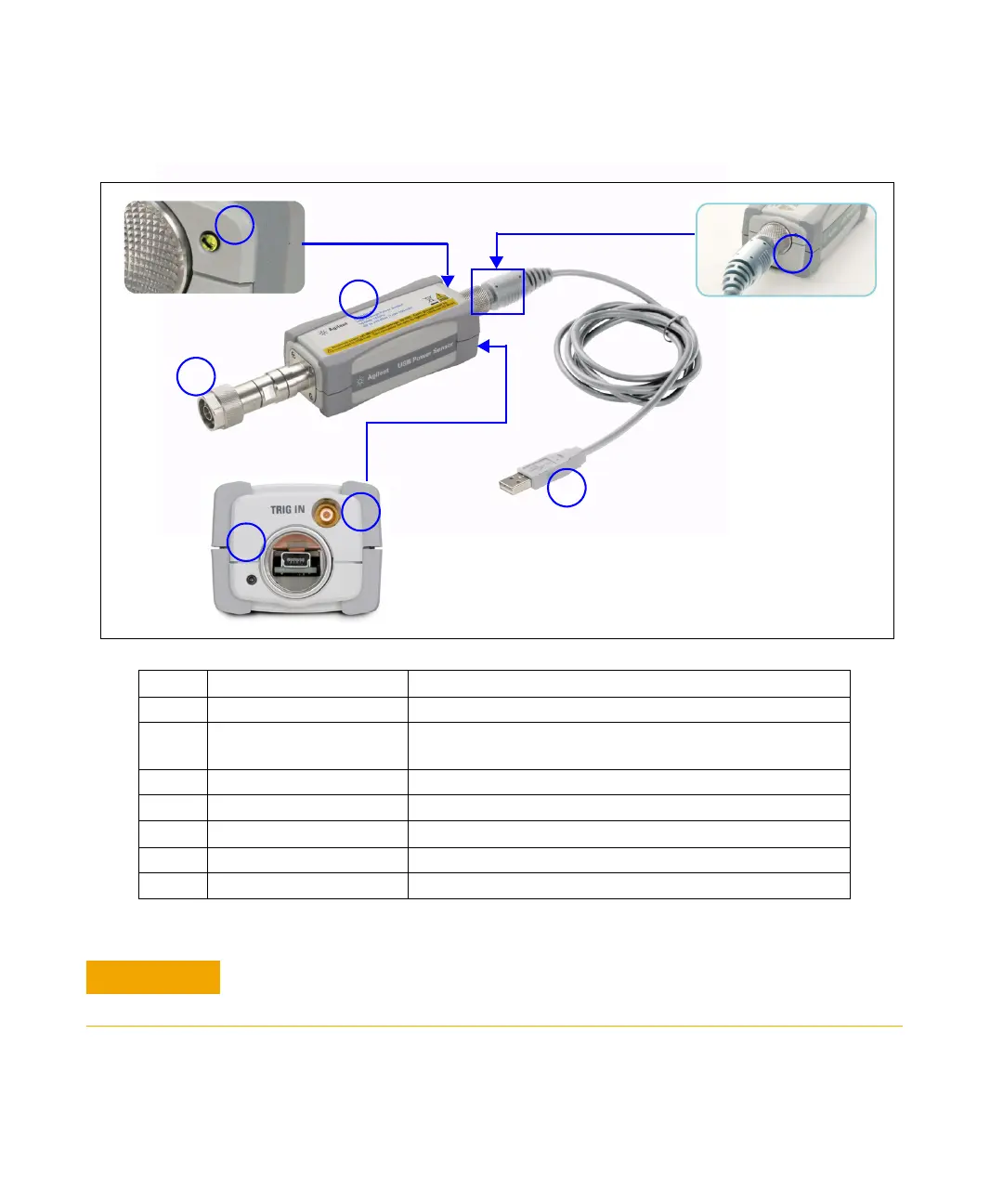
Power Sensor Overview
No. Part Functions
1 RF input port Allows RF/microwave input signal
2 LED indicator Indicates the states of the power sensor. Refer to “LED Indicator
Guide” for more information.
3 Sensor body Contains the core components of the power sensor
4 Physical lock mechanism Enables secure locking mechanism
5 USB compliant cable Connects the power sensor to the PC or other instruments
6 External trigger port Enables synchronization with external instruments or events
7 USB port Enables USB connectivity
DO NOT remove or disassemble the gold connector on the U2002H. This is a fixed body
part of the U2002H. Removing this connector will make the sensor defective.

 Loading...


