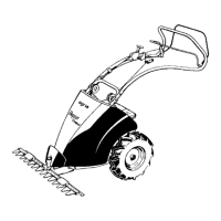
20 Grassland Mower Hopper 5000 Edition 02.97
3. Devices and Operating Elements
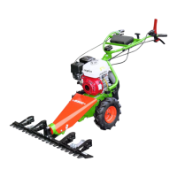
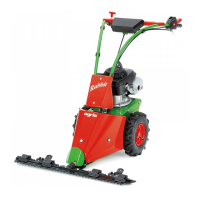
1 Linch pin
2 Drive wheel
3 Anti-winding-tube
4 Wheel shaft
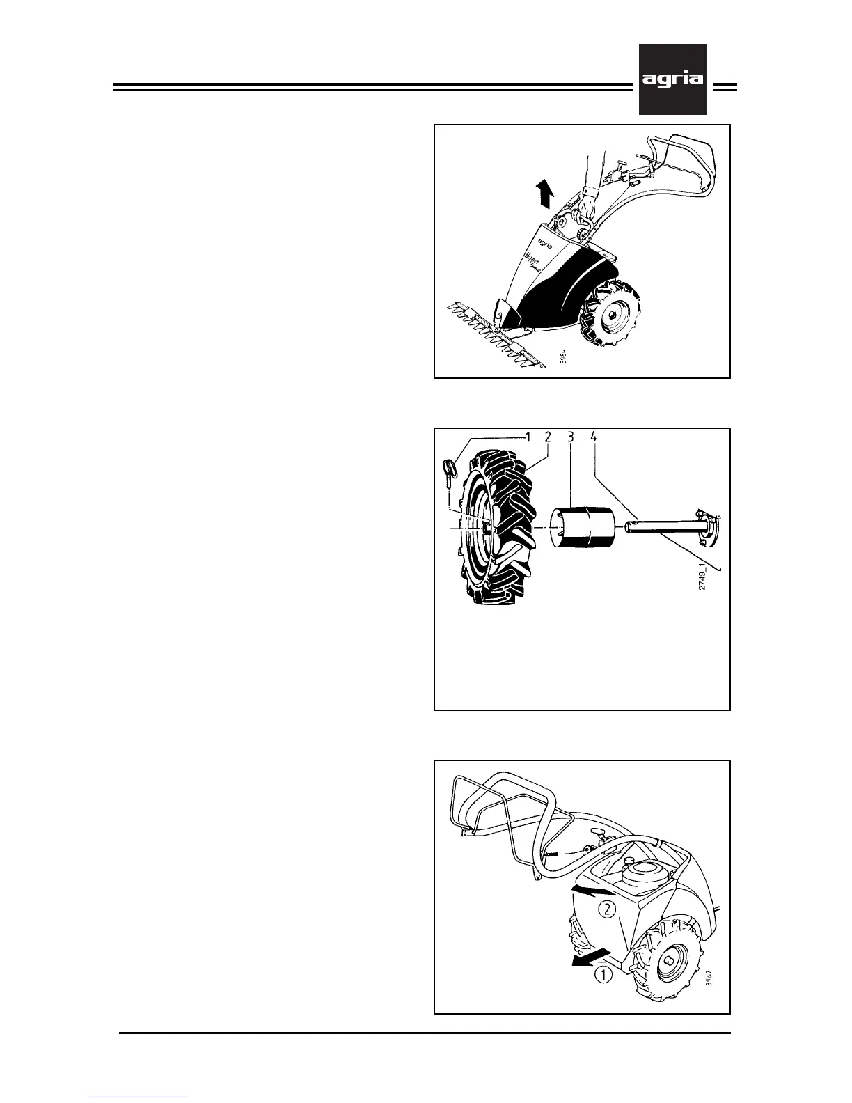
Handle to lift the Machine
The steering bar on the grassland
mower is shaped like a handle (A/6) to
allow the operator to lift the machine at
a favourable point of gravity.
Do not try to lift the mower on the plas-
tic panels!
Drive-wheels
The drive-wheels (2) are attached to the
wheel shaft (4) with linch pins (1). This
allows attaching and removing the
wheels without tools.
Anti-winding tubes (3) are fitted on both
ends of the wheel shaft. These prevent
grass from winding around the shafts.
Removing grass that has wound around
the shaft is easy: simply remove the
drive-wheels without tools and slide off
the tubes.
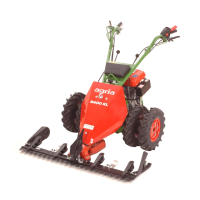
Engine Panel
The Comfort engine version is equipped
with a rear engine panel (A/17).
Remove this panel to inspect and serv-
ice the engine.
Removing the engine panel
l
Remove the grip nut and pull the
panel from the threaded pin to the rear
l
Remove the panel from bracket 2,
pulling it upwards at an angle and to-
wards the handlebar
Mounting the engine panel
l
To replace the panel, reverse the
above order.