108
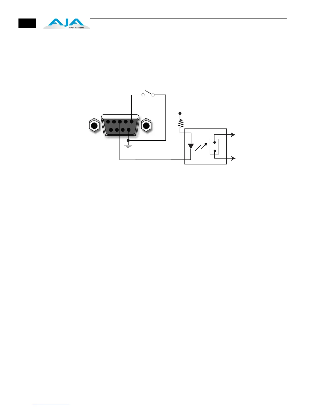
The following illustration shows typical external wiring to the GPI connector. The
GPI inputs require some kind of contact closure between the input pin and the
input ground pin to register the logic low that triggers the GPI input.
You can connect the outputs to TTL buffers that communicate the GPI output logic
levels to other devices. For example, you could use an opto-isolator controlling a
relay to activate other equipment as shown below.
Typical GPI Input and Output Connections
GPI Output 1
GPI
Input 1
GPI GND 1
+V
xmit+
xmit-
Optical Relay (SSR)
To Tally Lamp etc.