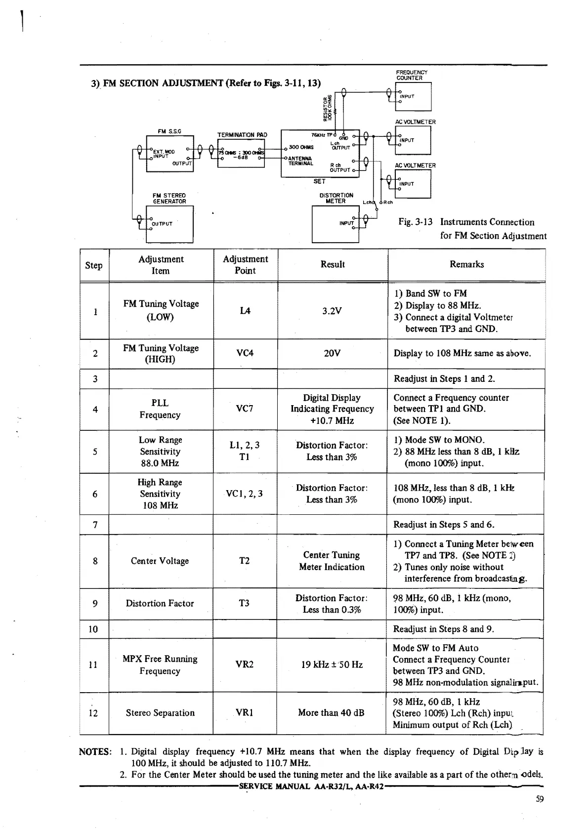
3)
FM
SECTION
ADJUSTMENT
(Refer
to
Figs.
3-11, 13)
FM
S.S.G
EXT.MOO
INPUT
FM
STEREO
GENERATOR
TERMINATION
PAO
ae:300
-6dB
76KHZ
TP
300
OHMS
ANTENNA
TERMINAL
SET
FREQUENCY
COUNTER
AC
VOLTMETER
OUTPUT
Fig. 3-13 Instruments Connection
for
FM
Section Adjustment
Step
Adjustment Adjustment
Result Remarks
Item
Point
1) Band
SW
to
FM
1
FM Tuning Voltage
lA
3.2V
2)
Display
to
88
MHz.
(LOW)
3)
Connect a digital Voltmeter
between TP3 and GND.
2
FM
Tuning Voltage
VC4
20V
Display
to
108
MHz
same
as
above.
(HIGH)
3
Readjust in Steps 1 and 2.
PLL
Digital Display Connect a Frequency counter
4
Frequency
VC7 Indicating Frequency between TP 1 and GND.
+10.7
MHz
(See NOTE 1).
Low Range
Ll,2,3
Distortion Factor:
I)
Mode
SW
to
MONO.
5
Sensitivity
Tl
Less
than
3%
2)
88 MHz less than 8 dB, I
kHz
88.0MHz (mono 100%) input.
High Range
Distortion Factor: 108 MHz, less than 8 dB, 1
kH1:
6
Sensitivity
VCI,
2, 3
Less than
3%
(mono 100%) input.
108
MHz
7
Readjust in Steps 5 and
6.
1) Connect a Tuning Meter beiw
een
8
Center Voltage T2
Center Tuning
TP7 and TP8. (See NOTE
J)
Meter Indication
2)
Tunes only noise without
interference from broadcasting.
9
Distortion Factor T3
Distortion Factor:
98
MHz,
60
dB, I kHz (mono,
Less than 0.3% 100%) input.
10
Readjust in Steps
8 and
9.
Mode
SW
to
FM
Auto
11
MPX
Free Running
VR2
19
kHz
±50
Hz
Connect a Frequency Counter
Frequency between TP3 and GND.
98
MHz
non-modulation signalio.put.
98
MHz,
60
dB, 1 kHz
12
Stereo Separation
VRl
More than
40
dB
(Stereo 100%) Leh (Reh)
input
•
Minimum output
of
Reh (Leh)
NOTES:
1.
Digital display frequency +10.7
MHz
means that when the display frequency
of
Digital
Dtplay
is
100
MHz,
it should be adjusted to 110. 7 MHz.
2.
For
the Center Meter should be used
the
tuning meter and the like available as a part
of
the other'Il
-0dels.
--------------~R.VICE
MANUAL AA-R.32/L,
AA-R.42--------------
59
•
 Loading...