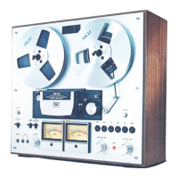
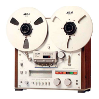
@ SUPPL Y
REEL
TABLE
® TAPE
TENSION
LEVER
Provides ideal
tape
tension.
® IMPEDANCE
ROLLER
IJ)
TIMER
START
SWITCH
When using
an
external
timer
(sold separately),
set
to
PLA Y
for
timed
playback
or
set
to
REC
for
absentee recording.
*
Before
turning
o n
the
power,
confirm
that
the
TIMER
START
Switch
is
at
the
proper
position.
If,
for
ex-
ample,
the
TI
MER
STAR
T
Switch
is
set
at
REC,
the
deck
will
automatically
start
recording
when
the
power
is
turned
on.
® VU METERS
(Left
and
Right)
lndicate
left
and
right
channel
recording
and
play-
back levels.
® POWER SWITCH
®
REEL
SIZE
SELECTOR
Set
to
"10"
when
using
10-1/2"
reels
and
to
"7"
when
using
7"
or
5"
reels.
@ HEADPHONE
JACK
Accommodates
8
ohm
impedance
type
stereo
head-
phones.
©
OUTPUT
LEVEL
CONTROL
Adjusts
output
level during
playback
and
the
head-
phone
output
volume.
Set
to
correspond
with
amplifier
input.
@
TAPE
MONITOR
SWITCH
Set
to
SOURCE
position
to
monitor
source
and
to
TAPE
position
for
playback
or
priva
te
head
phone
listening.
@
TRACK
SELECTOR
SWITCHES
(Left
and
Right
Channel Selectors)
Depress
left
or
right
selector
for
monaural
recording
or
playback
on
left
or
right channel.
For
stereo
recording
or
playback
depress
both
switches simul-
taneously.
*
Caution:
Be
sure
to
select
channels
prior
to
effecting
recording
or
playback
mode.
@ TAPE
SELECTOR
SWITCH
WIDE
RANGE
(In):
Set
to
this
position
when
using
Wide Range Tape.
LOW
NOISE
(Out):
Set
to
this
position
when
using
Low
Noise Tape.
*
See
TAPE
SELECTOR
on
page
8.
@
TAPE
SPEED
SELECTOR
Set
to
7-1
/2
or
3-3/4
in
ac
cor
ding
to
desired speed.
@
RECORDING
MUTE
When the
Recording
Mute
is
engaged signais will
not
be
recorded
on
the
tape.
REC
button
will flash
on
and
off
when
Recording
Mute is engaged.
@ MICROPHONE
INPUT
CONTROLS
(REC
LEVEL
MIC)
Used
for
adjusting
recording
input
level
for
micro-
phone
input
and
when
using
the
DIN
Jack.
The
inner
knob
is
for
the
left
channel,
and
the
outer
ring
for
the
right.
To
allow simple
Fade-In
and
Fade-Out,
the
left
and
right
contro!s
are
not
only
made
coaxial
but
are
of
the
friction
type
that
makes
them
turn
toge
th
er.
@ FIXE-BOBINE
INCORPORE
(gauche)
Pour
verrouiller la
bobine
en
place,
tirer
vers l'ex-
térieur
l'extrémité
du
fixe-bobine puis la
tourner
vers
la
droite
ou
vers
la
gauche.
@ PLATEAU DE
BOBINE
DEBITRICE
(~
LEVIER
DE
TENSION
DE
BANDE
Assure
une
tension
parfaite.
C6:
ROULEAU
D'IMPEDANCE
'7
1 COMMUTATEUR
DE
MISE
EN
MARCHE DE
MINUTERIE
(TIMER
START)
Mettre le
commutateur
sur
PLA
Y
pour
une
lecture
mise en
marche
à
l'aide
de la
minuterie
ou
sur
REC
pour
un
enregistrement
autonome,
lors de l'utilisa-
tion
d'une
minuterie
extérieure
(vendue
séparé-
ment).
*
Vérifier
que
le
commutateur
de
mise
en
marche
Je
minuterie
est
en
position
correcte,
avant
de
mettre
l'ap-
pareil
sous
tension
.
Par
exemple,
au
cas
oÙ
le
commuta
-
teur
TIMER
STAR
T
est
sur
la
position
REC,
la
platine
commencera
automatiquement
l'enregistrement
lorsque
l'appareil
est
mis
sous
tension.
® VU-METRES (gauche
et
droit)
Indiquent
les
niveaux
de
lecture
et
d'enregistrement
des
canaux
droit
et
gauche.
(9
INTERRUPTEUR
GENERAL
®
SELECTEUR
DETAILLE
DE BOBINE
Le
mettre
sur
"1
0"
lors de
l'utilisation
de
bobines
de
10-1/2"
et
sur
"7"
lors de
l'utilisation
de
bobines
de
7"
ou
5".
@
PRISE
DE CASQUE
(PHONE)
Prévue
pour
des casques
stéréo
du
type
à
impédance
de 8
ohms.
@ COMMANDE DE
NIVEAU
DE
SORTIE
(OUTPUT)
Permet
de régler le niveau de
sortie
à la
lecture
et
le
volume
de
sortie
des casques.
Effectuer
ce réglage
en
fonction
de
l'entrée
de
l'amplificateur.
@
COMMUTATEUR
DE
MONITEUR
DE BANDE
(MONITOR)
Le
régler
sur
la position SOURCE
pour
contrôler
la
source
et
sur
TAPE
pour
la
lecture
ou
l'écoute
in-
dividuelle.
@ COMMUTATEURS DU
SELECTEUR
DE PISTE
(Sélecteurs
des canaux
gauche
et
droit)
Appuyer
sur
le sélecteur
droit
ou
gauche
pour
un
enregistrement
ou une
lecture
monophonique
sur
le
canal
droit
ou
gauche.
Pour
un
enregistrement
ou
une
lecture
stéréo,
appuyer
simultanément
sur
les
deux
commutateurs.
*
Attention:
S'assurer
de
sélectionner
les
canaux
an-
térieurement
à la
lecture
ou
à
l'enregistrement.
@
COMMUTATEUR
DU
SELECTEUR
DE BANDE
WIDE
RANGE
(Position
enfoncée):
Le régler
sur
cette
position
lorsque des
bandes
à
gamme
étendue
sont
utilisées.
LOW
NOISE
(Position
non
enfoncée):
Le régler
sur
cette
position
lorsque des
bandes
à faible
bruit
sont
utilisées.
*
Voir
SELECTEUR
DE
BANDE
à la
page
8.
d~
SELECTEUR
DE VITESSE DE BANDE
Le
régler
sur
7-1/2
ou
3-3/4
selon
la
vitesse désirée.
Sicherung
nach
auBen
ziehen
und
sie
nach
links
oder
rechts
drehen.
@
ABLAUFBANDTELLER
® BANDZUGARM
Ermoglicht die ideale
Bandspannung.
®
IMPEDANZROLLE
IJ)
TIMER-STARTTASTE
Wenn Sie
einen
AuBen-
Timer
( wird
separat
varkauft)
benutzen,
stellen Sie
auf
PLA
Y
für
eine
zeitge-
steuerte
Wiedergabe
oder
auf
REC
für
eine
Auf-
nahme
wahrend
Ihrer
Abwesenheit.
*
Bevor
Sie
den
Strom
einschalten,
vergewissern
Sie
sich,
da~
die
Timer-Starttaste
in
der
rich
tigen
Stellung
ist.
Wenn
die
Taste
z.B.
auf
REC
gestellt
ist,
wird
das
Gerat
automatisch
mit
der
Aufnahme
beginnen,
sobald
Sie
den
Strom
einschalten.
®
VU-AUSSTEUERUNGSINSTRUMENT
(links
und
rechts)
Zeigen
den
Aufnahme-
und
Wiedergabepegel des
linken
und
rechten
Kanals an.
®
STROMSCHALTER
® SPULENG RÔSSE-WAHLSCHALTER
Bei
der
Verwendung
von
27 cm-Spulen
(10-1/2)
schalten
Sie
auf
"1
0"
und
bei 18 cm-(7)
oder
13 cm-Spulen
(5)
auf
"7''.
@ KOPFHÔRER-BUCHSE
Hier
konnen
Stereo-Kopfhorer
mit
einer
Impedanz
von
8
Ohm
angeschlossen werden.
©
AUSGANGSPEGELREGLER
Reguliert den Ausgangspegel
wahrend
der
Wieder-
gabe
und
die AusgangslautsHirke des
Kopfhorers.
Stellen Sie
den
Regler der Lautsprecher-Eingangs-
leistung
entsprechend
ein.
@
MONITORTASTE
Wenn Sie
wahrend
einer
Aufnahme
das Original
horen
mochten,
stellen Sie diese Taste
auf
SOURCE
und
auf
TAPE,
wenn
Sie die Wiedergabe
oder
über
die
Kopfhorer
horen
mochten.
@
SPURENWAHLHEBEL
(linke
und
re ch te Kanal-
wahltasten)
Drücken
Sie die
rechte
oder linke Wahltaste
für
die
Mono-Aufnahme
oder -Wiedergabe
auf
dem
linken
oder
rechten
Kanal.
Für
die
Stereo-Aufna-
hme
oder
-Wiedergabe drücken Sie beide
Tasten
gleichzei tig.
*
Achtung
:
Wahlen
Sie
die
Kanale
vor
der
Aufnahme
oder
Wiedergabe.
@ BANDW
AHLSCHAL
TER
WIDE
RANGE:
Wahlen
Sie
diese Stellung bei
der
Verwendung
von
Wide-Range-Bandern.
LOW
NOISE:
Wahlen
Sie
diese Stellung bei
der
Verwendung
von
Low-Noise-Bandern.
*
Siehe
"BANDWAHLSCHALTER"
aufSeite
8.
@ BAN DG ESCHWINDIG KEITS-W AHLSCHAL
TER
Der
gewünschten
Geschwindigkeit
entsprechend
auf
7-1/2
oder
3-3/4
stellen.
@ AUFNAHME-STUMMABSTIMMTASTE
Wenn Sie diese Taste wahrend
einer
Aufnahme
drücken,
werden
keine Signale
auf
das Band
auf-
 Loading...