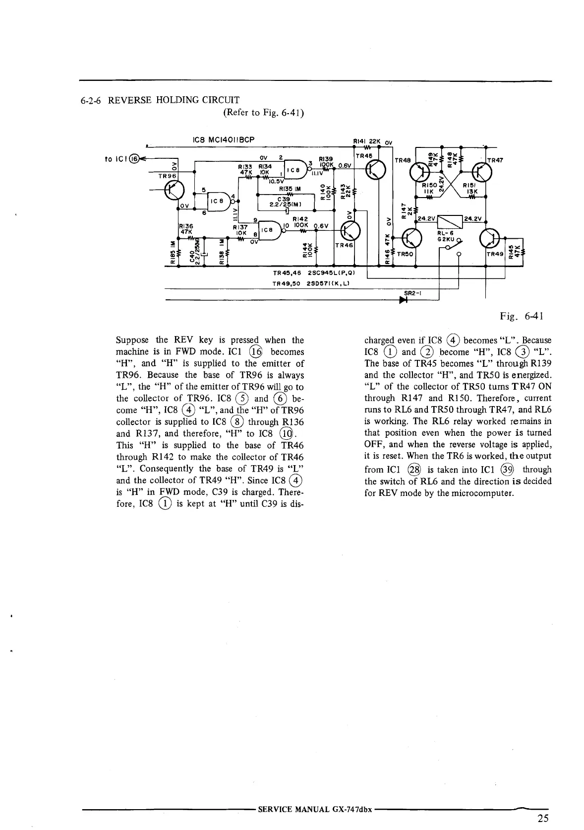
6-2-6 REVERSE HOLDING CIRCUIT
(Refer to Fig. 6-41)
ICB MCl4011BCP
Rl41 22K
OV
OV
2
Rl39
Rl33
Rl34
3
IOOK
0.6V
47K
IOK
I
ICS
5
IC
8
6
Rl'36
47K
:!
~
:!
.,
o"'
a,
!!!
.,,
"'
0::
u"'
ii:
"'
9
Rl37
IOI<
8
ov
10.5V
Rl35
IM
C39
2.2/2!S(Ml
,ca
TR46
TR4!5,46
2SC94!SL(P,Ql
TR49,50
2S0!571(K,Ll
Suppose the REV key
is
pressed when the
machine
is
in
FWD
mode. ICI @ becomes
"H",
and
"H"
is supplied to the emitter
of
TR96. Because the
base
of TR96
is
always
"L",
the
"H"
of
the emitter
of
TR96
will
go
to
the collector
of
TR96.
IC8
Q)
and @
be-
come
"H",
IC8
8)
"L",
and the
"H"
of
TR96
collector
is
supplied to
IC8
® through
Rl
36
and
Rl37,
and therefore, "H" to
IC8
@.
This
"H"
is
supplied to the
base
of
TR46
through
RI42
to make the collector
of
TR46
"L".
Consequently the
base
of
TR49
is
"L"
and the collector
of
TR49
"H".
Since
IC8
@)
is
"H"
in
FWD
mode, C39
is
charged. There-
fore,
IC8
(D
is
kept at "H" until C39
is
dis-
,.
,-.
..
..,
:!
0::
SR2-I
Fig.
6-41
charged even
if
IC8
@)
becomes
"L".
Because
IC8
(D
and
G)
become
"H",
IC8
G)
"L".
The
base
of
TR45 becomes
"L"
through
RI
39
and the collector
"H",
and TRS0
is
energized.
"L"
of
the collector
of
TRS0 turns TR47
ON
through R147 and RISO. Therefore, current
runs to RL6 and TRS0 through TR47, and RL6
is
working. The RL6 relay worked remains
in
that position even when the power
is
turned
OFF, and when the
reverse
voltage is applied,
it
is
reset.
When
the TR6
is
worked,
the
output
from ICl
@
is
taken into ICI @ through
the switch
of
RL6 and the direction
is
decided
for
REV
mode by the microcomputer.
----------------
SERVICE MANUAL GX-747dbx
----------------
25
 Loading...