Page 35 of 80
Install the Control Cable Connectors and Controller Socket
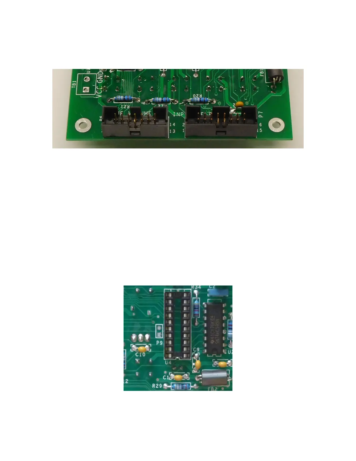
Insert the 14-pin cable connector, P6. Make sure to install the 14-pin connector in the
orientation shown in Figure 23.
Figure 23-14 and 16 pin cable connector installation
Solder two corner pins, and make sure that you’ve got it right one more time
before you solder the remainder of the pins.
Check to see that the connector sits flat on the board. If it doesn’t, melt the solder
joint on one or both corner pins and adjust the connector until it does sit flat.
Insert the 16-pin cable connector, P7. Make sure that the orientation of the connector
matches Figure 23..
Solder two corner pins, and make sure that you’ve got it right one more time
before you solder the remainder of the pins.
Check to see that the connector sits flat on the board. If it doesn’t, melt one or
both corner pins and adjust the connector until it does sit flat.
Next, install and solder the 20-pin socket into the silkscreen into U4. Make sure that the
indented feature in the socket matches the indentation in the silk screen. (In Figure 24
we’ve added a gray line to the socket to emphasize the indentation).
Figure 24-showing socket orientation
It’s best to hold the socket in place by bending over two corner pins in a direction that
won’t encourage shorts to adjacent traces. If that makes you uncomfortable, you can: