Page 65 of 80
Section 8: Preliminary Final Assembly
Wire and install the front panel input connector
Identify the shielded cable that originates at TB7 and TB8 of the input selector PCB.
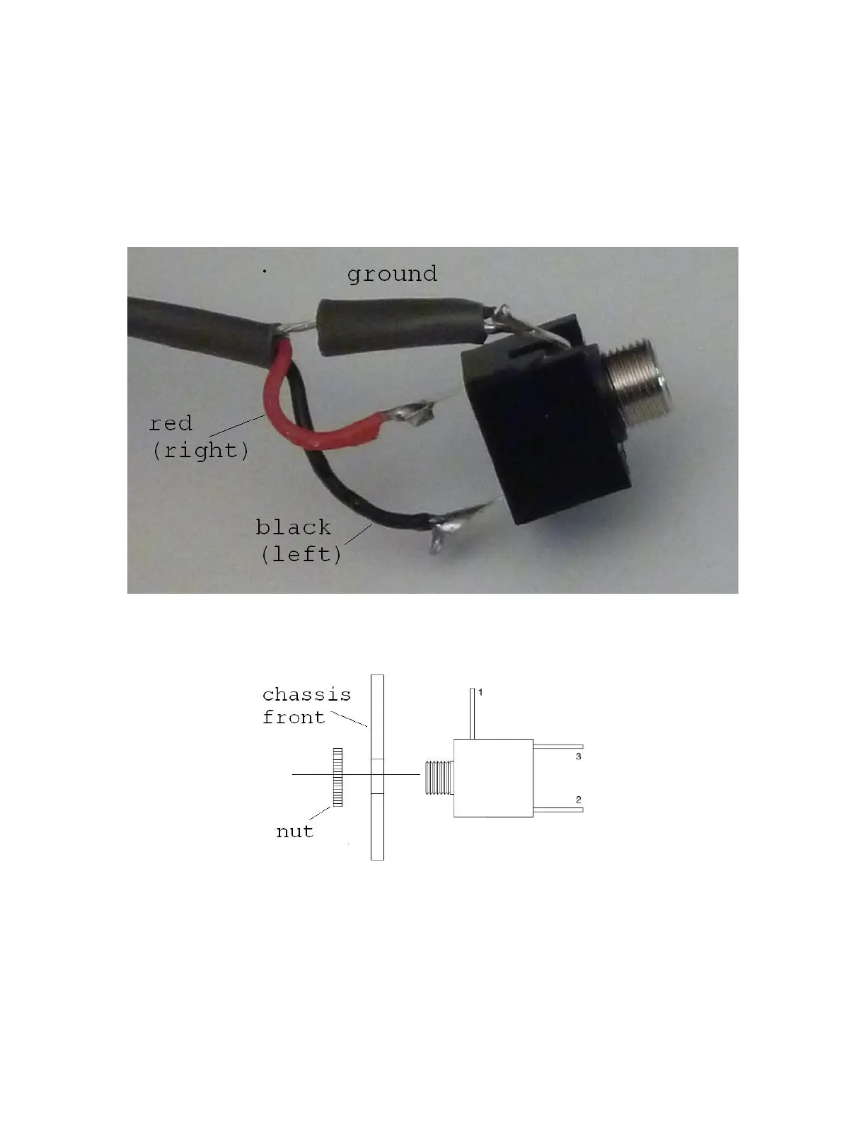
Solder the free end to one of the 1/8” phono jacks, connecting the wires as shown in
Figure 46.
Figure 46-Connecting wires to front panel (FP) 1/8" phono jack
Insert the jack into hole marked “Front Panel”. Secure it with the provided nut, per the
detail in Figure 47. The orientation of the jack is not important.
Figure 47-Inserting 1/8" jacks in the front panel
Install the headphone jack
Install the second 1/8” phono jack into the hole marked with the headphone pictogram,
fastening it per the detail in Figure 47. The headphone jack will have no wires at this
time. It is there to support an optional headphone amplifier (a future project).