Page 56 of 80
Note about H1 and H2
Holes on the board for H1 and H2 do not receive components. They are placed for future
expansion, and are not used at this time.
Take a Break
You’ve earned it. You’ve just completed a big job. Congratulations. Take a break. I mean
it! You’ll feel better.
Section 7: Assembling the Tone-Volume-Balance Board
This section details the process of building the Tone-Volume-Balance circuit board.
Carefully empty the contents of the envelope marked “PR-102 Tone Volume” into a
broad soup bowl. A picture of the completed tone volume board may be found at the end
of this section.
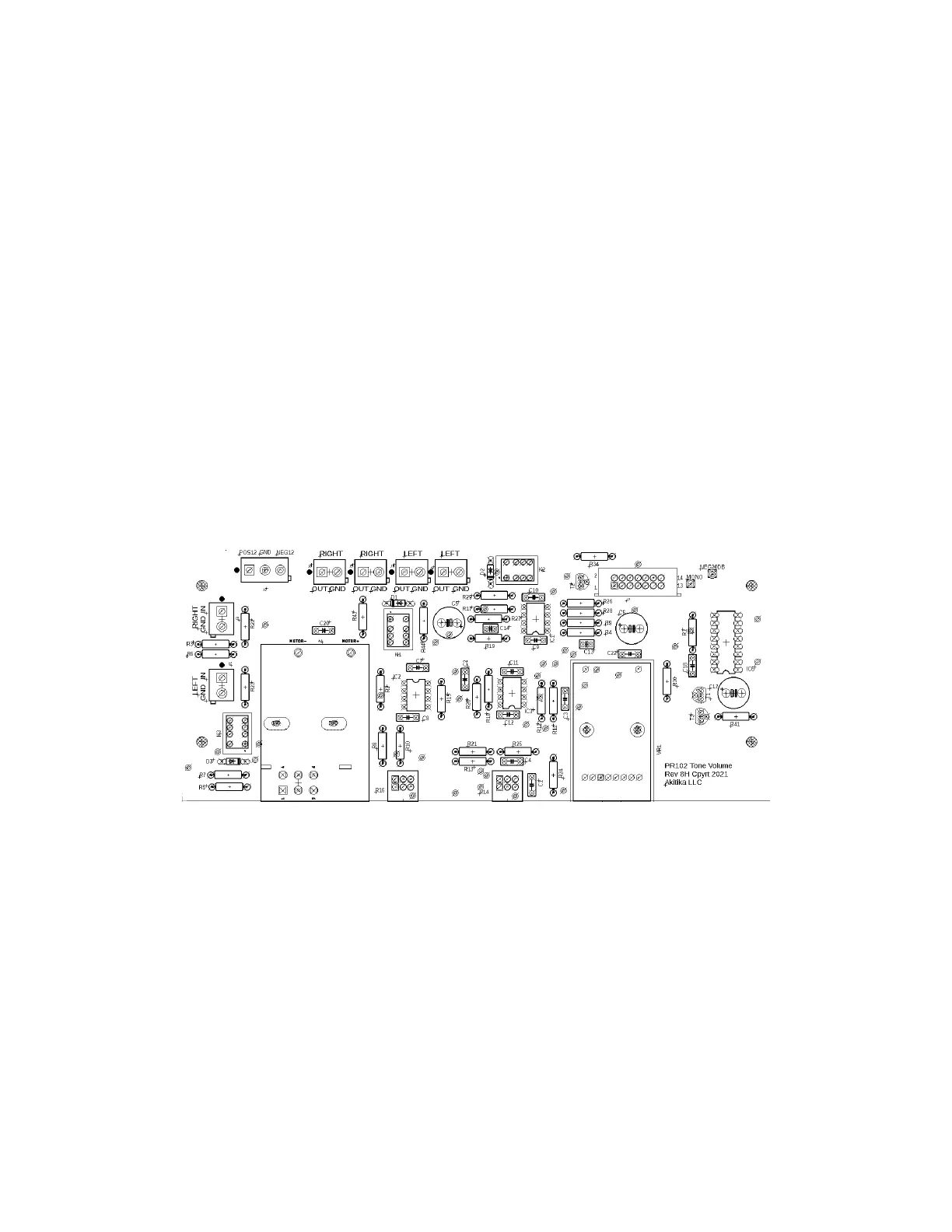
Please compare the PCB you have with the silk-screen below to make sure they match.
If they do not match, you may have an older version of the Tone Volume board,
as described in revision 1p17 of the manual. In that case, please build from 1p17.
If they do match, continue building using the latest rev 2pXX manual.
Figure 37-Silkscreen side of the tone volume board shows component locations
Install the Resistors
As before, you install the resistors by placing the body on the silk screen side of the
board, and the leads through the indicated holes. Bend the leads over on the back of the
board to keep the resistors snugly against the board until you solder them in place. Try to
bend the leads in a direction that avoids solder bridges between traces.
We recommend the following procedure:
1. Identify the group of (like valued) resistors that you plan to install. You’ll find
that resistors of the same value are often (but not always) collected together with
tape on both ends.
2. I recommend cutting the leads near the tape, then bending them in the lead
bending jig.