Page 43 of 80
Section 6: Assembling the Input Selector Board
Carefully empty the contents of the envelope marked “PR-101 Input Selector” into a
broad soup bowl. Note that the envelope may also say PR-102 Input Selector. This part of
the design did not change between the PR-101 and the PR-102.
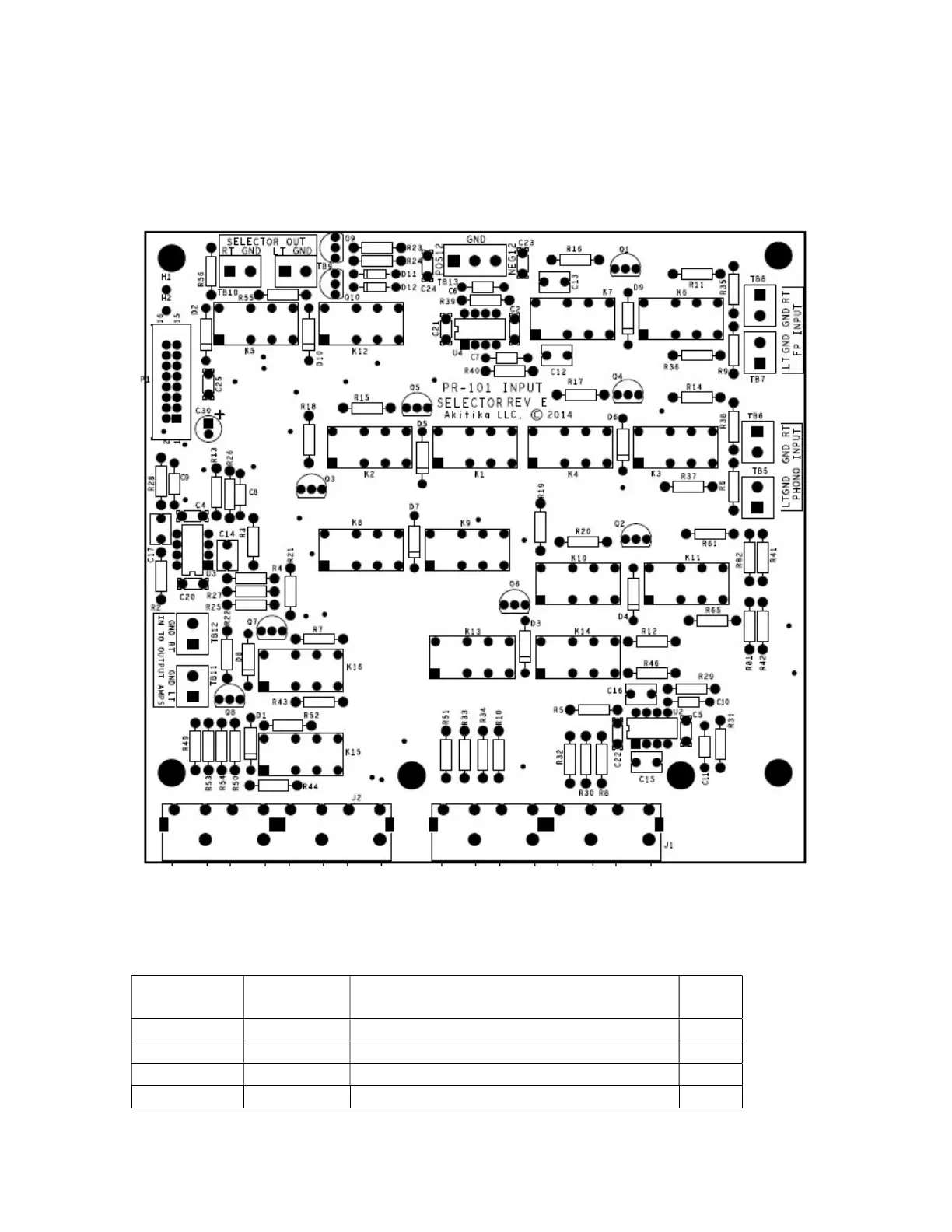
Figure 30-Silkscreen side of the Input Selector Board shows component locations
Install the Resistors
Install the resistors using the same procedures outlined in the previous section. If you’re
using a lead bending jig, all the resistors should be bent at a width of 0.45”.
Designation Value Color Code Done
Brown, black, black, orange, brown
Brown, black, black, orange, brown
Brown, black, black, orange, brown
Brown, black, black, orange, brown

 Loading...