Page 50 of 80
Tip to seat the connector:
1. Line up the back row of pins first.
2. Push on one side of the connector to get that side seated.
Push on the other side of the connecto
r toget the other side seated.
Make sure the connectors are seated flat on the board before you solder them in place.
The ground leads will take a generous amount of heat to solder well.
Designation Value Description Done
2 rows of 4 female connectors
Install the Input Jack Shield
The bag containing the PCB’s has one small PCB remaining. It is the input jack shield.
You’ll attach it to the board with a pair of small brackets and 4 4-40x1/4” Phillips head
zinc-plated SEMs screws (with built-in lock-washers). The following figures show the
details on an otherwise mostly bare input selector board, so you can easily see how it all
goes together. Note that your board will already have the components populated.
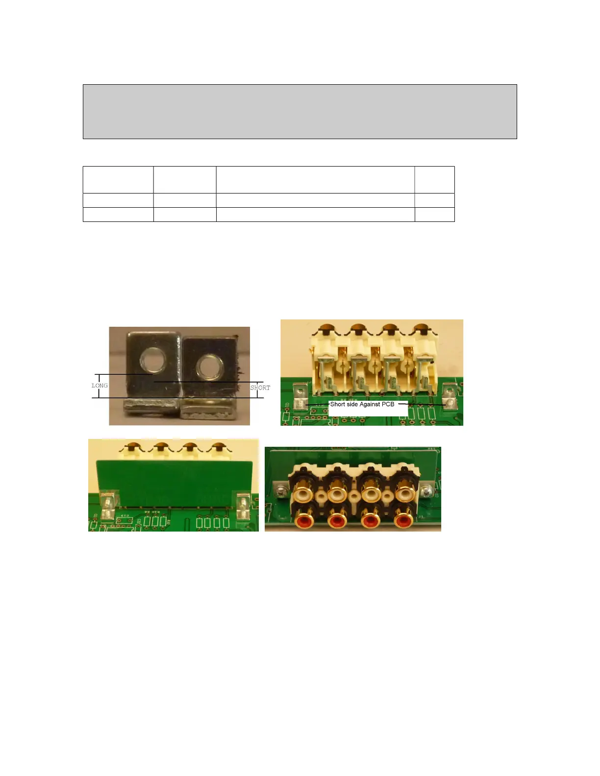
Figure 33-Mounting the input connector shield
The first picture shows that legs of the brackets are not symmetrical. The hole in one of
the legs (the short side) is closer to the fold than the hole in the other leg (the long side).
Make sure that the short side touches the PCB.
If you’ve gotten it backwards then there won’t be any daylight between the shield and the
board. If one bracket is one way, and the other the other way, then the space between the
shield and the PCB will be uneven.
These Connectors Are Not Populated
The connectors listed here are not populated. In a later step, you will wire directly to the
PC board.

 Loading...