Page 58 of 80
Install the Motor Driver IC
Install IC6. The IC’s pin rows typically start out a bit wider than the matching holes in
the PCB. You can push a row of the IC pins against the table, first on one row, and then
on the other. Just press them in gently and do a trial fit so you don’t go too far.
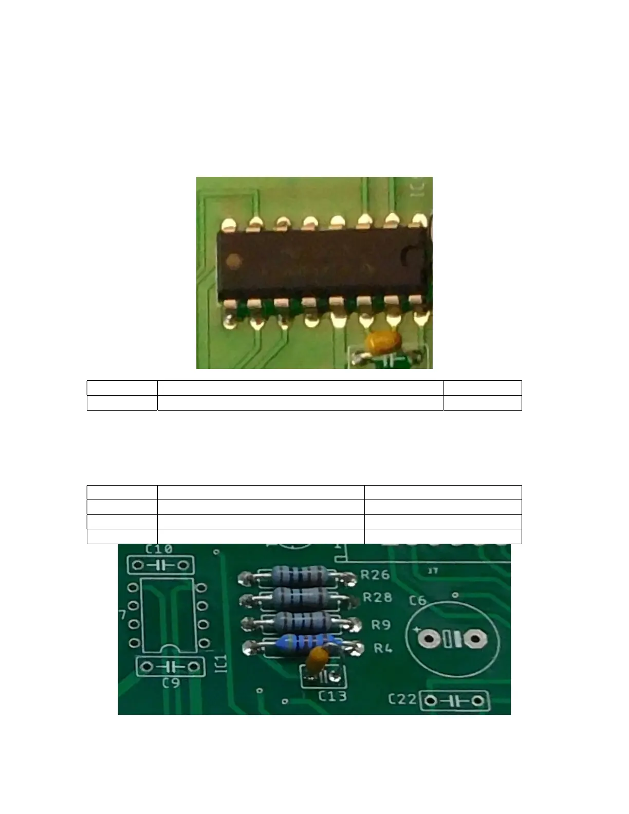
Make sure you get the orientation of IC6 correct, matching the notch in the part to the
notch in the silk-screen. The notched end of IC6 goes next to C17.
Figure 38-orientation of IC6
Install the Diodes
Install the diodes. Make sure to match the white band on the diode to the white band on
the PCB. That white band marks the cathode of the diode, and the diode must be inserted
with the correct orientation to work correctly.
Figure 39-C13 and C14 installation (C13 shown)

 Loading...