Fan Tray LEDs
140 7750 SR-a4 and SR-a8 Installation Guide
You must supply your own DC power cables. Verify that they are compliant with your local
safety code. PSUs have no field-replaceable parts. You must replace the entire unit in the
event of a failure.
Refer to Installing, Wiring, and Connecting a –48 VDC PSU on page 98 for requirements and
information regarding preparing DC power cables.
Fan Tray LEDs
Fan trays are chassis-specific.
• The 7750 SR-a4 5-RU chassis requires the SR-a4 fan tray, which houses four axial
fans.
• The 7750 SR-a8 7-RU rack requires the SR-a8 fan tray, which houses six axial fans.
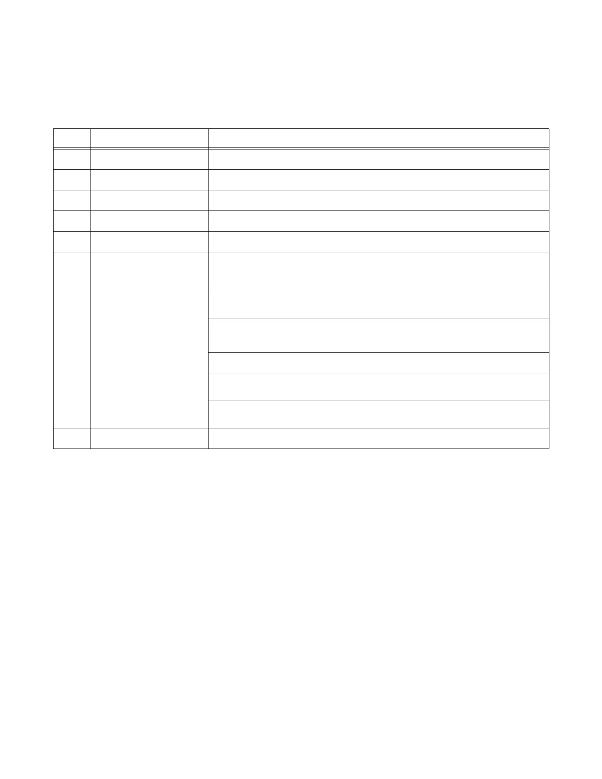
Table 56: 7750 SR-a –48 VDC PSU Description
Key Part Description
1 Handle Used to remove power supply after the latch (Key 7) is unlocked
2 Fan Cooling fan for the PSU
3 Ground terminal M4 screw
4 Power connector screw Left terminal stud (Batt terminal) for connection to –48 VDC battery cable
5 Power connector screw Right terminal stud (RTN terminal) for connection to 0 VDC return cable
6LED Unlit: The DC power input is below the specified minimum to turn on the
PSU.
Green (slow blink): The PSU is in standby mode. Standby output is
operating within normal parameters. The main output is disabled.
Green (solid): The standby and main outputs are operating within normal
parameters.
Yellow (slow blink): A warning condition has been detected on the PSU.
Yellow (solid): A fault condition has been detected on the PSU.
Red (solid): An incorrect PSU has been inserted in the shelf.
7 Latch lock Secures the PSU in place. Press the latch lock to the left to unlock the PSU.