Appendix D: CPM-a Pinout Assignments
7750 SR-a4 and SR-a8 Installation Guide 213
The on-board configuration program can be accessed from a terminal or a PC running a
terminal emulation program.
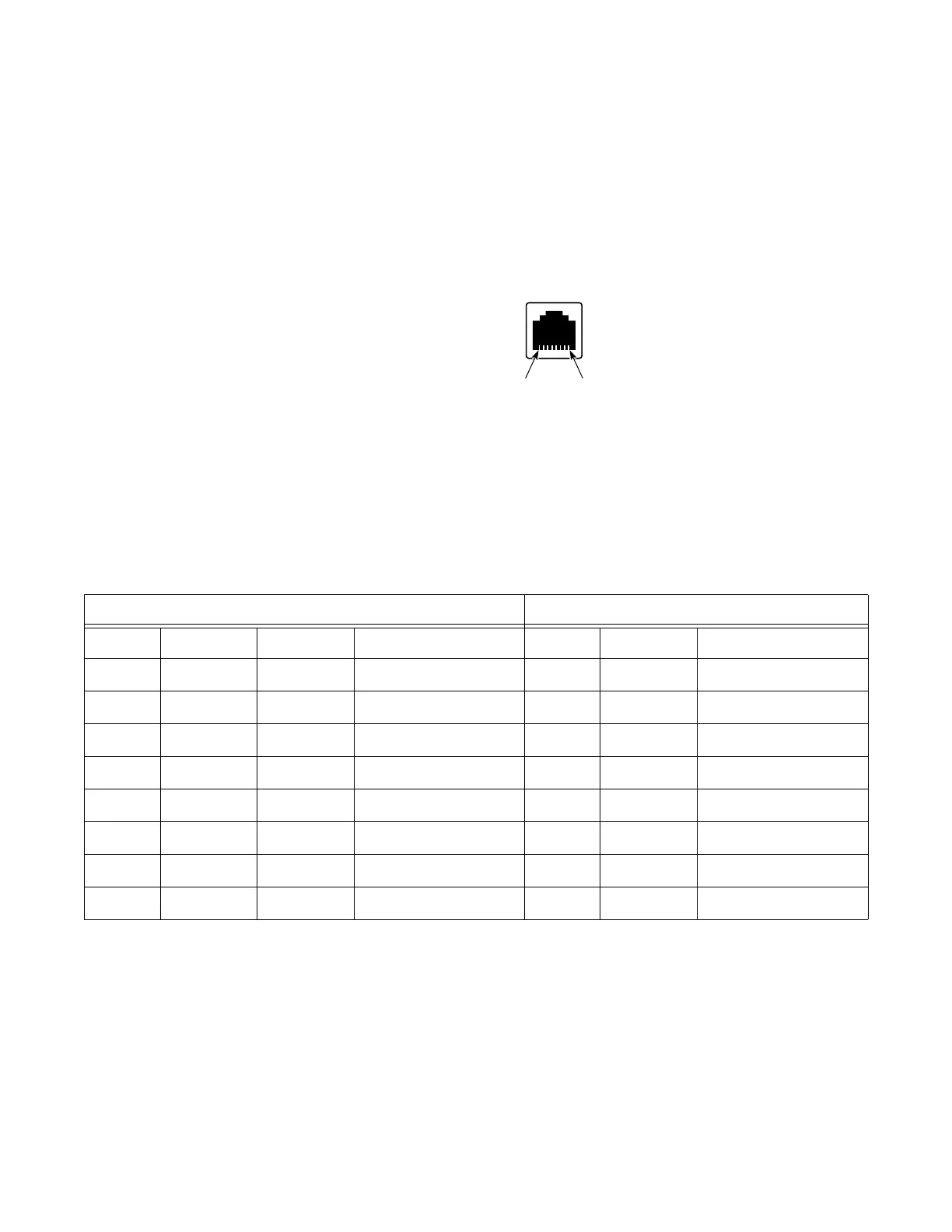
See Figure 78 for information about the Console Port pin numbers.
Figure 78: Console Port Pin Numbers
Console Port Pinouts RS-232 DTE Mode
Table 106 describes the Console port pin assignments when the CPM is in DTE mode.
Console Port Pinouts RS-232 DCE Mode
Table 107 describes the Console port pin assignments when the CPM is in DCE mode.
Table 106: Console Port Pinouts— RS-232 DTE Mode: RJ-45 to DB9 Cable
RJ-45 DB9
Pin Signal Direction Description Pin Signal Description
1 RTS Output Request to send 8 CTS Clear to send
2 DTR Output Data terminal ready 6 DSR Data set ready
3 TXD Output Transmit data 2 RXD Receive data
4 GND — Signal ground 1 GND Signal ground
5 GND — Signal ground 5 GND Signal ground
6 RXD Input Receive data 3 TXD Transmit data
7 DSR Input Data set ready 4 DTR Data terminal ready
8 CTS Input Clear to send 7 RTS Request to send