49
GB
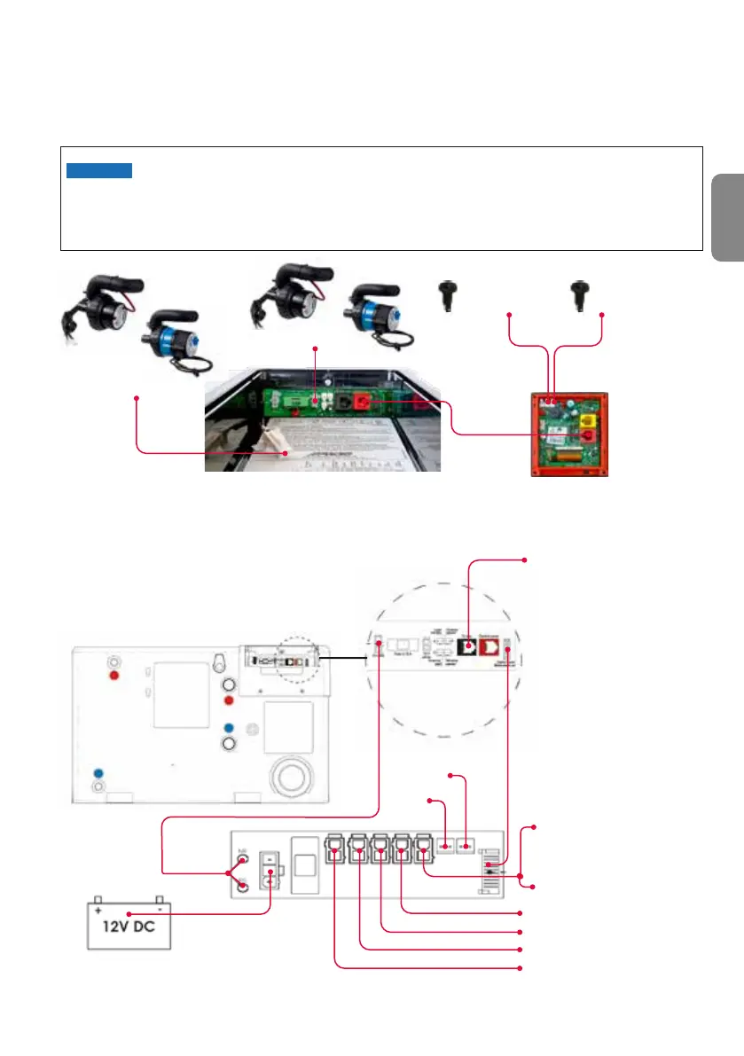
OUT 12V DC
CONNECTED
TO HEATER
8. Cable connection
connected to the red connector on the Alde Control Panel, a splitter (part number 36120-01) and adapter
(part number 39050-00175) will be needed. Only 1 x AC can be connected to the Alde heating system.
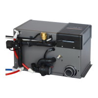
8.1 Option card
Products marked (*) are optional.
Never fasten 12 V or sensor cables with 230 V cables. Keep cables apart. If cables are bundled
together, the risk of malfunction during use increases.
To avoid malfunction, use only original Alde cables.
Fig. 21, Connection, option board (part number 3020023)
Sensor zone 1
3010238
Sensor zone 2
3010238
Fig. 20, Cable connections in service hatch
Control panel
3030112
Pump zone 2
Pump zone 1
* Truma AC el. iNet connects
to TIN bus port
* Climate control system works with:
- Truma Aventa Comfort
- Truma Aventa Eco
- Truma Saphir Compact RC
- Truma Saphir Compact
(series >23091001)
Saphir Compact needs a Truma
adapter 39050-00175
Printed circuit board
on the Alde Compact
3030/3030 Plus boiler
Option board for Alde Compact 3030/3030 Plus
JP2: Booster fan, for single zone
JP3: Engine pre heat pump
JP4: Alde Flow pump/ 3-way valve
JP5: Booster fan, for dual zones
FUSE
3.15 A
Eis Ex
Gas level
sensor
JP5: For single zones,
12 V Signal for indication
of any gas (R122)