17
2 Separation process 2.2 General
Single phase separators
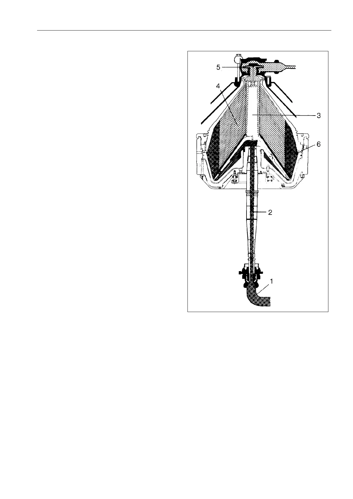
The flow of the product through the machine is
shown in the adjoining figure.
Product is fed to the inlet bend (1) for further
conveyance through the hollow bowl spindle (2)
to the distributor (3) and onwards through the
distribution holes in the discs (4). The separation
takes place in the spaces between the discs. The
liquid is forced along the upper sides of the discs
towards the bowl centre, leaves the bowl and is
reforwarded by the impeller (5). The rest –
sediment – moves along the undersides of the
discs towards the bowl periphery where the
sediment settles in the sediment space (6).
Legend
1. Inlet bend
2. Bowl spindle (hollow)
3. Distributor
4. Bowl discs
5. Impeller – separated liquid
6. Sediment space
2.2.1 Throughput
The throughput is directly dependent on the flow
resistance in the separator and subsequent
devices and piping as well as on the height of the
collecting tanks above the outlet.
The throughput is regulated by adjusting the inlet
pressure.
G0695711
 Loading...