31
3 Mechanical function 3.6 Axial seals – cooling system
The sealing element and wear ring must always
be flushed with liquid when the bowl rotates. The
seals are therefore supplied, through special
channels, with flushing water, and during the
CIP-period with CIP-liquid.
3.7 Axial seals –
cooling system
(The illustrations in this chapter show twin phase
separators)
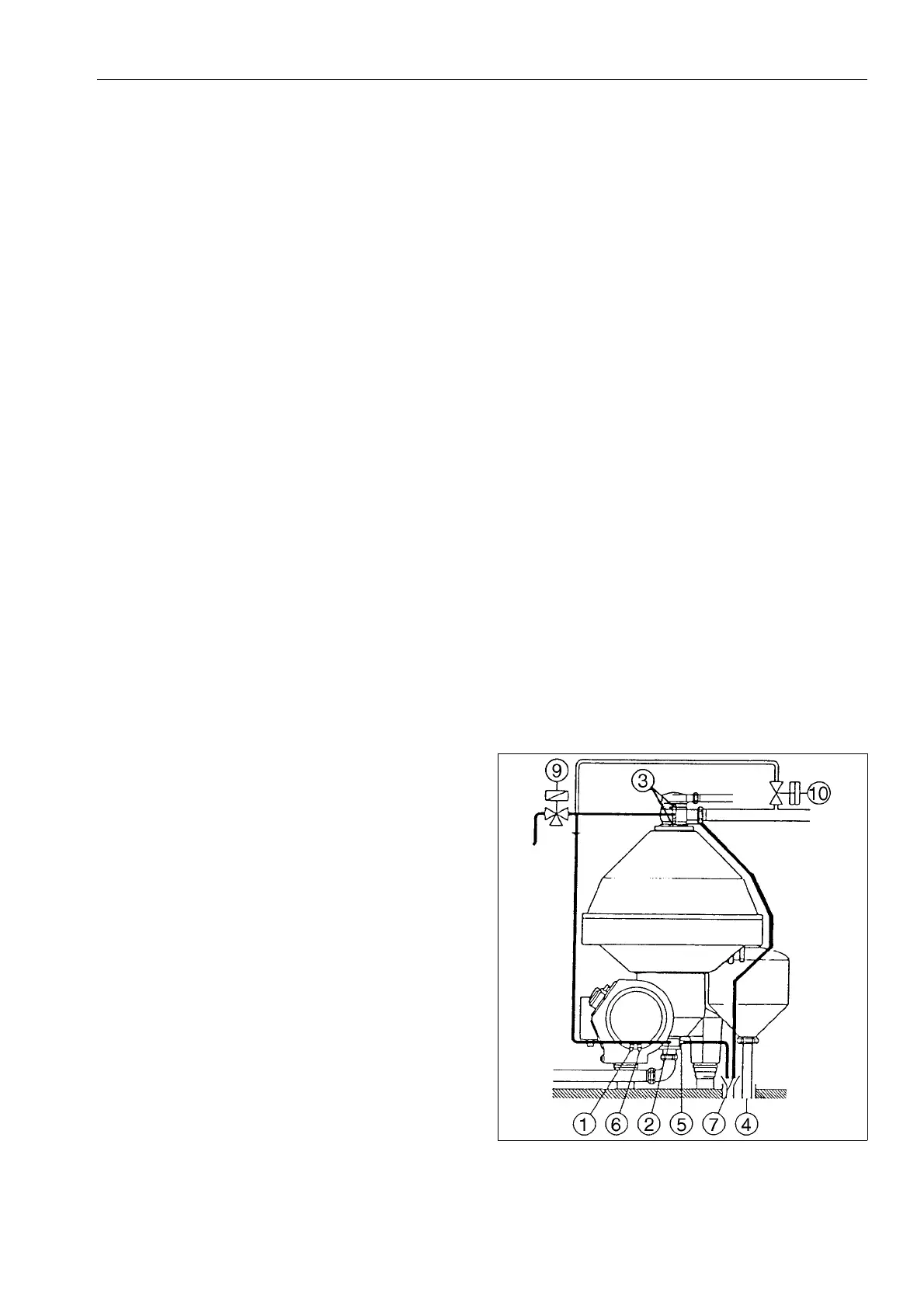
During starting / separation / stopping periods
During the starting / separation / stopping periods,
cooling water is fed to the seals through
connections (2 and 3).
The cooling water from the outlet seals
discharges through the sediment outlet (4) and
pipe (7). From the inlet seals the water flows out
through outlet (5).
Water pressure and flow – see “Connection list” in
Installation Manual
.
1, 6 Cooling coil for oil bath.
2, 3 Cooling water inlet
4 Sediment outlet / cooling water outlet
5, 7 Indication tube for cooling water
9Valve *)
10 Valve
*) Normally included in the control unit cabinet.
Note: The indication tubes (5 and 7 in the figure)
provides an easy means of visual indication that
water is being supplied to the seals. Note that the
pipes (5 and 7) will also serve as an indication
pipe for seal leakage, if any.
G0695231
 Loading...