12
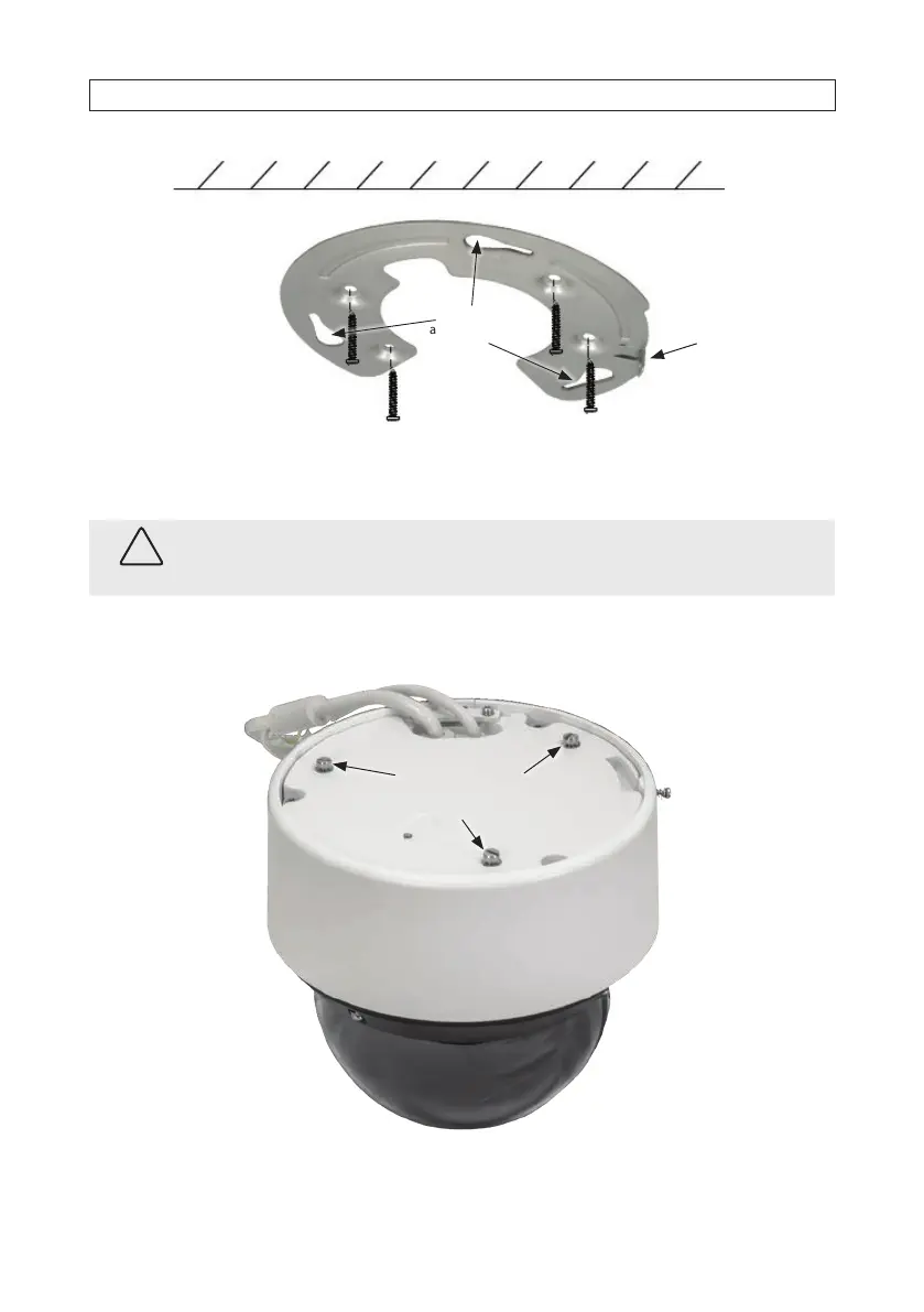
Slots (3) on
adapter plate
Tab for lock
screw
8. Route LAN, power, and accessory extension cables to the installation location and connect them to the camera drop cable, as
needed. Protect all connections from contamination. See “2.6 Connecting drop cables” on page 18 for more information.
CAUTION
Failure of this product due to contamination of drop cable connections is considered an installation error, and voids the
warranty of the product.
9. Position the camera on the adapter plate such that the three raised screw heads (see below) in the camera base t into the
three slots in the plate, and then rotate the camera clockwise to fully seat the screw heads in the slots.
Align raised screw
heads (3) with slots on
the adapter plate
Adapter plate
lock screw
SECTION 2: INSTALLATION