13
Version 1.01
Parts name and functions
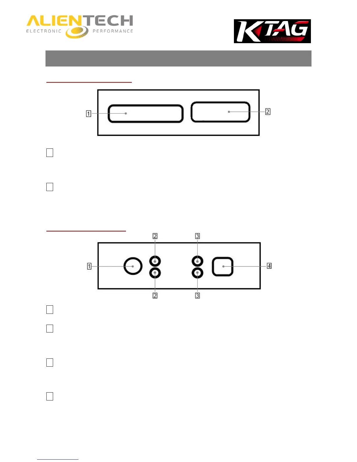
Right side of the tool
1 IDC 26 Connector (BDM/JTAG)
To connect the cables supplied with the tool. Refer to the Operating Manuals dedicated to the various protocols
available in the K-Suite software to know which cable to connect to the type of ECU on which you want to work.
2 DB15 Connector (Boot Mode)
To connect the cables supplied with the tool. Refer to the Operating Manuals dedicated to the various protocols
available in the K-Suite software to know which cable to connect to the type of ECU on which you want to work.
Left side of the tool
1 AC Adaptor connector
2 Status LEDs
The blue LED (ECU/ON, top) lights up when the tool is communicating with the ECU. The orange LED (KEY/ON,
bottom) lights up when the tool simulates Key on/Key off.
3 Status LEDs
The red LED (POWER, top) lights up when the tool is connected to AC Adaptor. The green LED (DATA, bottom) lights
up when the tool is connected to the computer through the USB cable.
4 USB port
To connect the tool to the computer.