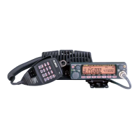
DR-620
Service Manual
CONTENTS
SPECIFICATIONS
1) G ENE RAL .............................................................................2
2) TRA NSM ITTER...................................................................2
3) R EC EIV ER
........................................................................... 3
CIRCUIT DESCRIPTION
1) VHF Reception....................................................................4
2) UHF Reception....................................................................5
3) FM Reception.......................................................................5
4) V/V (VHF-VHF) Dual Reception......................................6
5) U/U (UHF-UHF) Dual Reception
....................................
6
6) VHF Squelch Control
.........................................................6
7) UHF Squelch Control.........................................................6
8) Transmit Signal Path ..........................................................7
9) VHF Transmit Signal Path .................................................7
10) UHF Transmit Signal Path.................................................7
11) VHF Tx APC Circuit............................................................7
12) UHF Tx APC Circuit............................................................8
13) VHF PTT Circuit...................................................................8
14) UHF PTT Circuit..................................................................8
15) VHF PLL................................................................................8
16) UHF PLL................................................................................9
17) Power-on Circuit.................................................................9
SEM ICON DUCTOR DATA
1) M5218FP (XA 0068)......................................................... 10
2) NJM78L05UA (XA0098) ................................................. 10
3) NJM7808FA (X A0102).................................................... 10
4) TC4S66F (X A0115)......................................................... 11
5) AN8010M (XA 0119).........................................................11
6) BU4052BF (X A0236)....................................................... 11
7) TA75S01F (XA0332)........................................................ 12
8) TC4W53FU (XA0348)..................................................... 12
9) TA31136FN (XA0404)..................................................... 12
10) LA4425A (XA0410).......................................................... 13
11) NJM2904V (XA0573)....................................................... 13
12) NJM2902V-TE1 (XA0596) ............................................. 13
13) S-80845ALMP-EA9-T2 (XA 0620)
...............................
14
14) TK10931V (XA0666)........................................................ 14
15) BR24C64F-E2 (XA 066 9)
...............................................
15
16) LC75884W (X A 08 99 )
..................................................... 16
17) M51132FP (XA 0900)....................................................... 17
18) M30620FCAGP (XA0913/XA0949)...................... 17~19
19) M38503M2H667FP (XA 0914)
...............................
20~21
20) M64076AGP (X A0 915)...................................................22
21) S-816A50AMC (X A0925)
...............................................
23
22) NJM78M05DL1A (X A 0947)
..........................................
23
23) Transistor, Diode, and LED Outline Drawings.... 24~25
24) LCD Connection........................................................26~27
EXPLODED VIEW
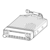
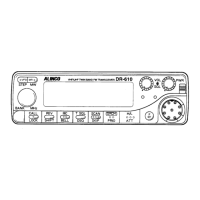
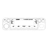
1) Front V iew
........................................................................... 28
2) Bottom View ....................................................................... 29
PARTS LIST
Front Unit.................................................................... 30~31
LED U n it..............................................................................31
Main U nit.....................................................................31~42
Mechanical Parts..............................................................42
Packing Parts..................................................................... 42
Accessories (Screw S et).................................................42
ADJUSTM ENT
1) Adjustment S po t...............................................................43
2) Adjustment M ode..............................................................44
3) VHF Adjustment Specification.......................................45
4) UHF Adjustment Specification.....................................46
5) VHF Test Specification....................................................47
6) UHF Test Specification....................................................48
PC BOARD VIE W
1) Front Side A ........................................................................49
2) Front Side B ........................................................................49
3) Main Side A ........................................................................50
4) Main Side B ........................................................................ 51
FRONT SCHEMATIC D IA G R A M ...................................52
MAIN SCHEMATIC D IA G R A M ........................................53
FRONT BLOCK D IA G R A M ..............................................54
MAIN BLOCK D IA G R AM ...................................................55
ALINCO,INC.